前言 BlogOS 是Philipp Oppermann 用Rust语言 编写的面向x86架构 的简单操作系统 。
《ARM v8之旅》 将作为 湖南大学2022年操作系统课程实验 笔记 。详细的解析 请参考 rust写个操作系统:课程实验blogos移至armV8深度解析
参考文章
一、环境配置
参考代码:下载
本文以Windows Subsystem for Linux 2 为环境,可参考 Windows Subsystem for Linux 2 的艺术
输入以下命令
1 curl --proto '=https' --tlsv1.2 -sSf https://sh.rustup.rs | sh
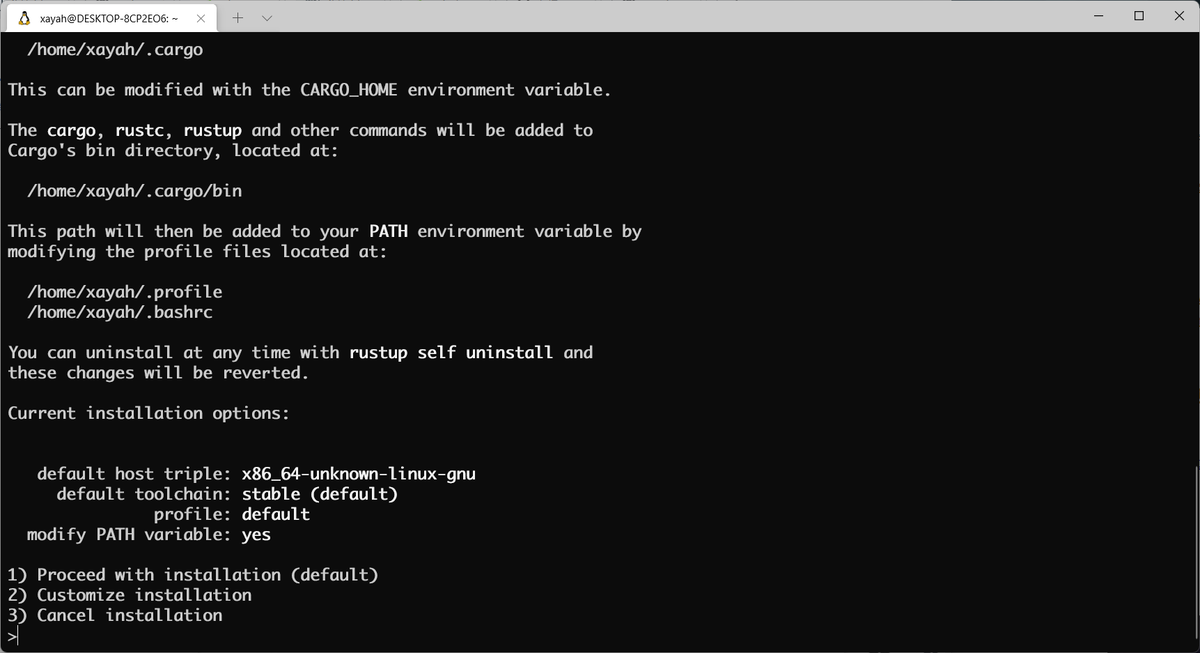
若网络正常 ,则会出现以下输出 ,键入1,执行默认安装 。
安装完成 后,激活Rust环境
查看版本
根据文档 ,实验需要用到Nightly版本
安装GCC
1 sudo apt-get install gcc
安装相关工具
1 cargo install cargo-binutils rustfilt
若安装GCC后仍无法正常cargo install cargo-binutils rustfilt,请尝试将软件源 更换为阿里源 (参见 Windows Subsystem for Linux 2 的艺术 GCC 。
2. 添加ARM v8支持 键入以下命令
1 rustup target add aarch64-unknown-none-softfloat
3. 安装QEMU模拟器 键入以下命令
1 sudo apt-get install qemu qemu-system-arm
安装必要环境
1 sudo apt-get install libncursesw5 libpython2.7 axel
创建交叉编译工具链 目录
1 mkdir ToolChain && cd ToolChain
使用axel 多线程下载工具链 AArch64 ELF bare-metal target (aarch64-none-elf)
1 axel -n 32 -a https://developer.arm.com/-/media/Files/downloads/gnu-a/10.3-2021.07/binrel/gcc-arm-10.3-2021.07-x86_64-aarch64-none-elf.tar.xz
解压
1 tar -xf gcc-arm-10.3-2021.07-x86_64-aarch64-none-elf.tar.xz
由于我们的目标是编写一个操作系统 ,所以我们需要创建一个独立于操作系统 的可执行程序 ,又称独立式可执行程序 (Freestanding Executable)或裸机程序 (Bare-metal Executable)。
这意味着所有依赖于操作系统的库 我们都不能使用 。比如std中的大部分内容(io, thread, file system, etc…)都需要操作系统的支持,所以这部分内容我们不能使用。
但是,不依赖于操作系统 的Rust 的语言特性 我们还是可以继续使用的,比如:迭代器 、模式匹配 、字符串格式化 、所有权系统 等。这使得Rust 依旧可以作为一个功能强大 的高级语言 ,帮助我们编写操作系统 。
新建项目 回到Home目录
新建名为rui_armv8_os的项目
1 cargo new rui_armv8_os --bin --edition 2021
进入rui_armv8_os目录
创建实验所需文件
1 touch src/panic.rs src/panic.rs src/start.s aarch64-qemu.ld aarch64-unknown-none-softfloat.json
创建.cargo文件夹
创建.cargo/config.toml
1 touch .cargo/config.toml
使用VSCode 打开
VSCode 安装Rust 、Rust-Analyzer 插件
编辑src/main.rs
1
2
3
4
5
6
7
8
9
10
11
12
13
14
15
16
17
18
19
#![no_std] // 不使用标准库 #![no_main] // 不使用预定义入口点 use core::{arch::global_asm, ptr}; // 导入需要的Module mod panic; global_asm!(include_str!("start.s")); #[no_mangle] // 不修改函数名 pub extern "C" fn not_main() { const UART0: *mut u8 = 0x0900_0000 as *mut u8; let out_str = b"AArch64 Bare Metal"; for byte in out_str { unsafe { ptr::write_volatile(UART0, *byte); } } }
编辑src/panic.rs
1
2
3
4
5
6
use core::panic::PanicInfo; #[panic_handler] fn on_panic(_info: &PanicInfo) -> ! { loop {} }
编辑src/start.s
1
2
3
4
5
6
7
8
9
10
11
12
13
14
.globl _start .extern LD_STACK_PTR .section ".text.boot" _start: ldr x30, =LD_STACK_PTR mov sp, x30 bl not_main .equ PSCI_SYSTEM_OFF, 0x84000002 .globl system_off system_off: ldr x0, =PSCI_SYSTEM_OFF hvc #0
编辑aarch64-qemu.ld
1
2
3
4
5
6
7
8
9
10
11
12
13
14
ENTRY(_start) SECTIONS { . = 0x40080000; .text.boot : { *(.text.boot) } .text : { *(.text) } .data : { *(.data) } .rodata : { *(.rodata) } .bss : { *(.bss) } . = ALIGN(8); . = . + 0x4000; LD_STACK_PTR = .; }
编辑aarch64-unknown-none-softfloat.json
1
2
3
4
5
6
7
8
9
10
11
12
13
14
15
16
17
18
19
20
21
22
23
24
25
26
27
28
29
30
31
32
{ "abi-blacklist": [ "stdcall", "fastcall", "vectorcall", "thiscall", "win64", "sysv64" ], "arch": "aarch64", "data-layout": "e-m:e-i8:8:32-i16:16:32-i64:64-i128:128-n32:64-S128", "disable-redzone": true, "env": "", "executables": true, "features": "+strict-align,+neon,+fp-armv8", "is-builtin": false, "linker": "rust-lld", "linker-flavor": "ld.lld", "linker-is-gnu": true, "pre-link-args": { "ld.lld": ["-Taarch64-qemu.ld"] }, "llvm-target": "aarch64-unknown-none", "max-atomic-width": 128, "os": "none", "panic-strategy": "abort", "relocation-model": "static", "target-c-int-width": "32", "target-endian": "little", "target-pointer-width": "64", "vendor": "" }
编辑.cargo/config.toml
1
2
3
4
5
[unstable] build-std = ["core", "compiler_builtins"] [build] target = "aarch64-unknown-none-softfloat.json"
编辑Cargo.toml
1
2
3
4
5
6
7
8
9
10
11
12
13
14
15
16
17
18
19
20
21
22
[package] name = "rui_armv8_os" version = "0.1.0" edition = "2021" authors = ["Rui Li <rui@hnu.edu.cn>"] # See more keys and their definitions at https://doc.rust-lang.org/cargo/reference/manifest.html [dependencies] # eh_personality语言项标记的函数,将被用于实现栈展开(stack unwinding)。 # 在使用标准库的情况下,当panic发生时,Rust将使用栈展开,来运行在栈上活跃的 # 所有变量的析构函数(destructor)——这确保了所有使用的内存都被释放。 # 如果不禁用会出现错误:language item required, but not found: `eh_personality` # 通过下面的配置禁用栈展开 # dev时禁用panic时栈展开 [profile.dev] panic = "abort" # release时禁用panic时栈展开 [profile.release] panic = "abort"
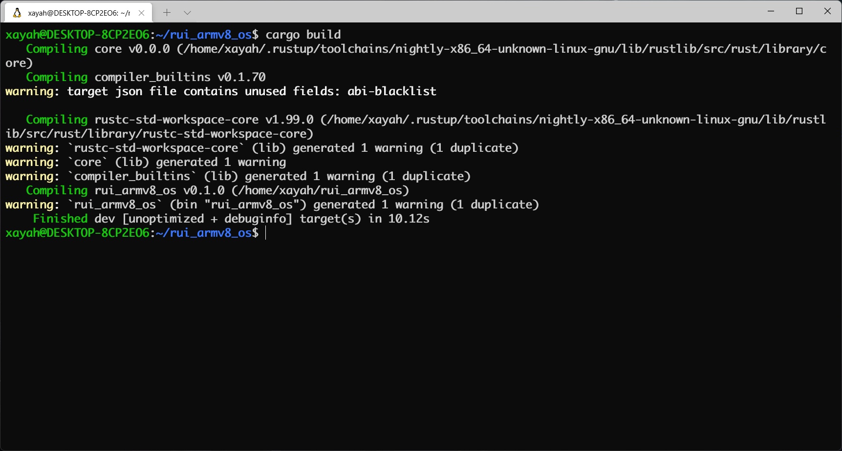
编译与运行 在项目根目录 下执行
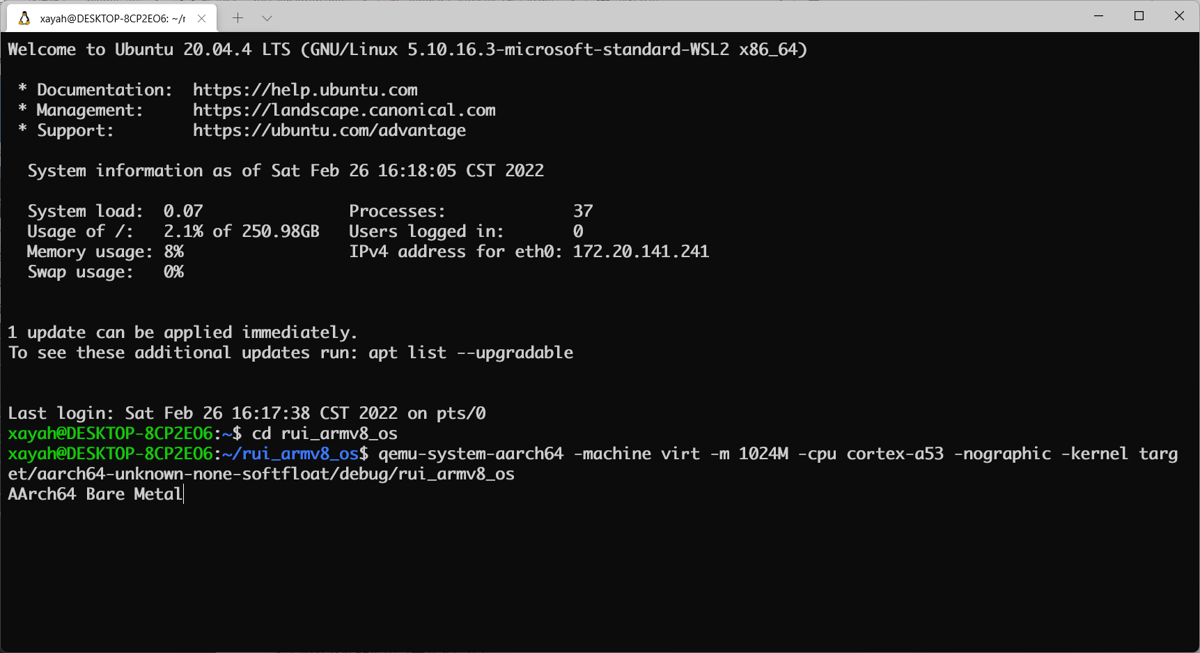
运行
1 qemu-system-aarch64 -machine virt -m 1024M -cpu cortex-a53 -nographic -kernel target/aarch64-unknown-none-softfloat/debug/rui_armv8_os
调试
QEMU进入调试,启动调试服务器,默认端口1234
关闭 之前运行的终端 ,打开一个新的终端 ,进入rui_armv8_os目录
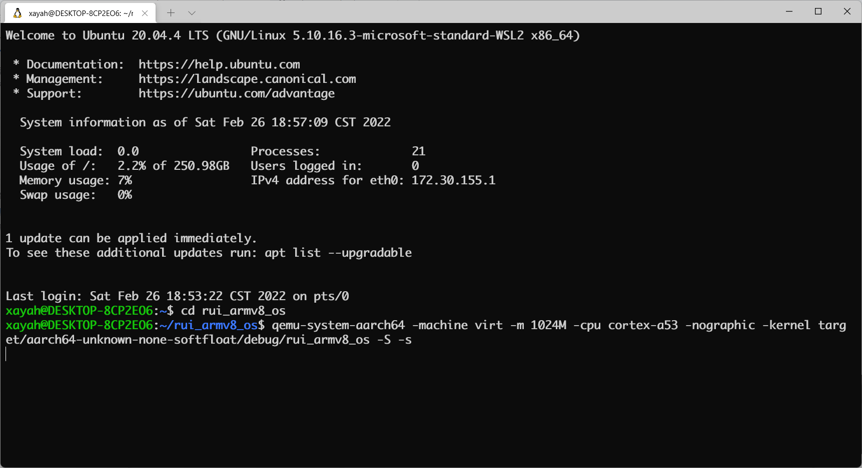
启动调试
1 qemu-system-aarch64 -machine virt -m 1024M -cpu cortex-a53 -nographic -kernel target/aarch64-unknown-none-softfloat/debug/rui_armv8_os -S -s
重新打开 一个终端 ,进入工具链 bin目录
1 cd ~/ToolChain/gcc-arm-10.3-2021.07-x86_64-aarch64-none-elf/bin
导出工具链路径 临时变量
1 export ToolChainPath=`pwd`
进入rui_armv8_os目录
配置临时工具链环境 (这里的$ToolChainPath即是刚刚导出的临时变量)
1 export PATH=$ToolChainPath:$PATH
启用GDB调试客户端
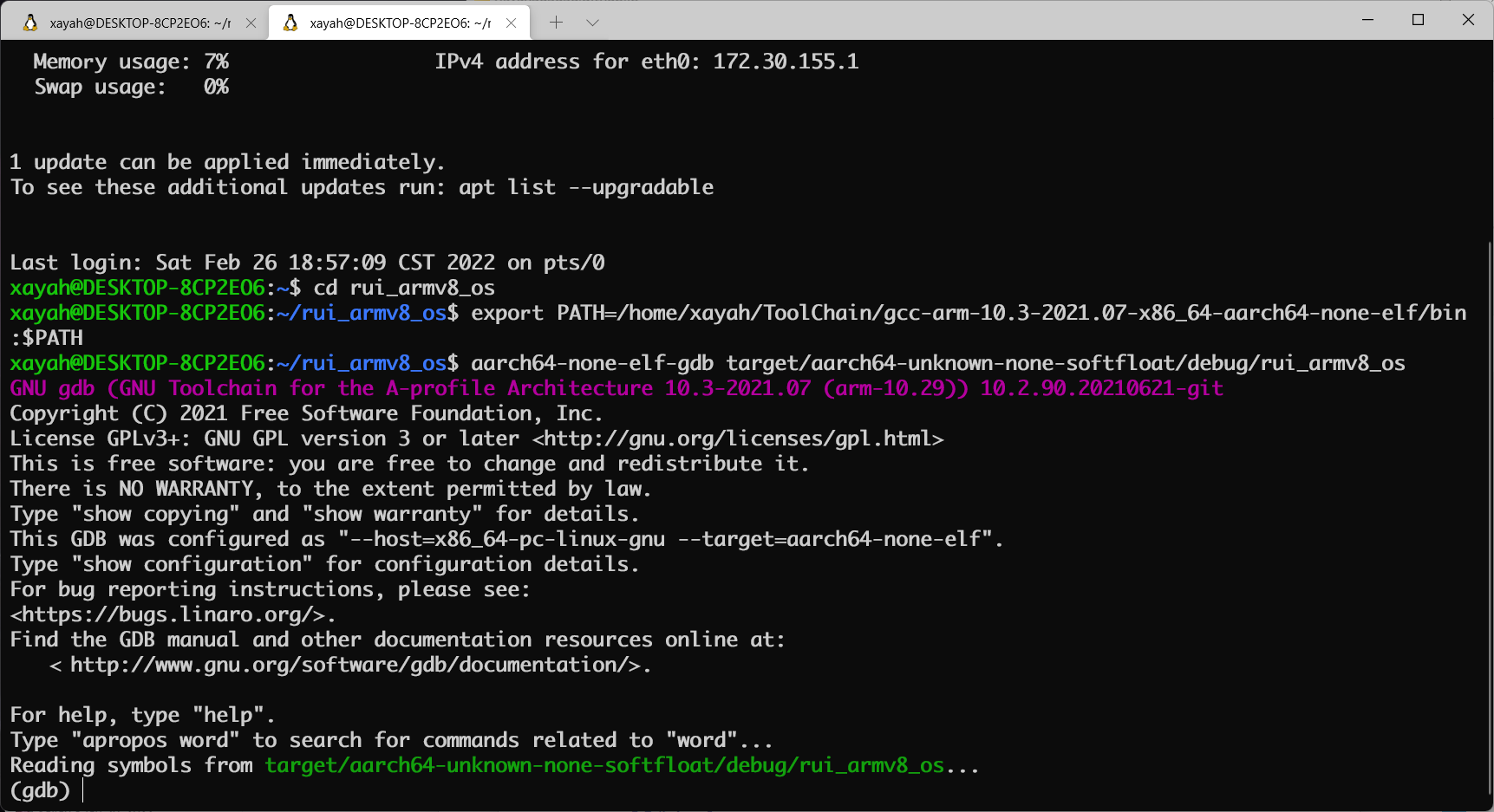
1 aarch64-none-elf-gdb target/aarch64-unknown-none-softfloat/debug/rui_armv8_os
设置调试参数 ,开始调试
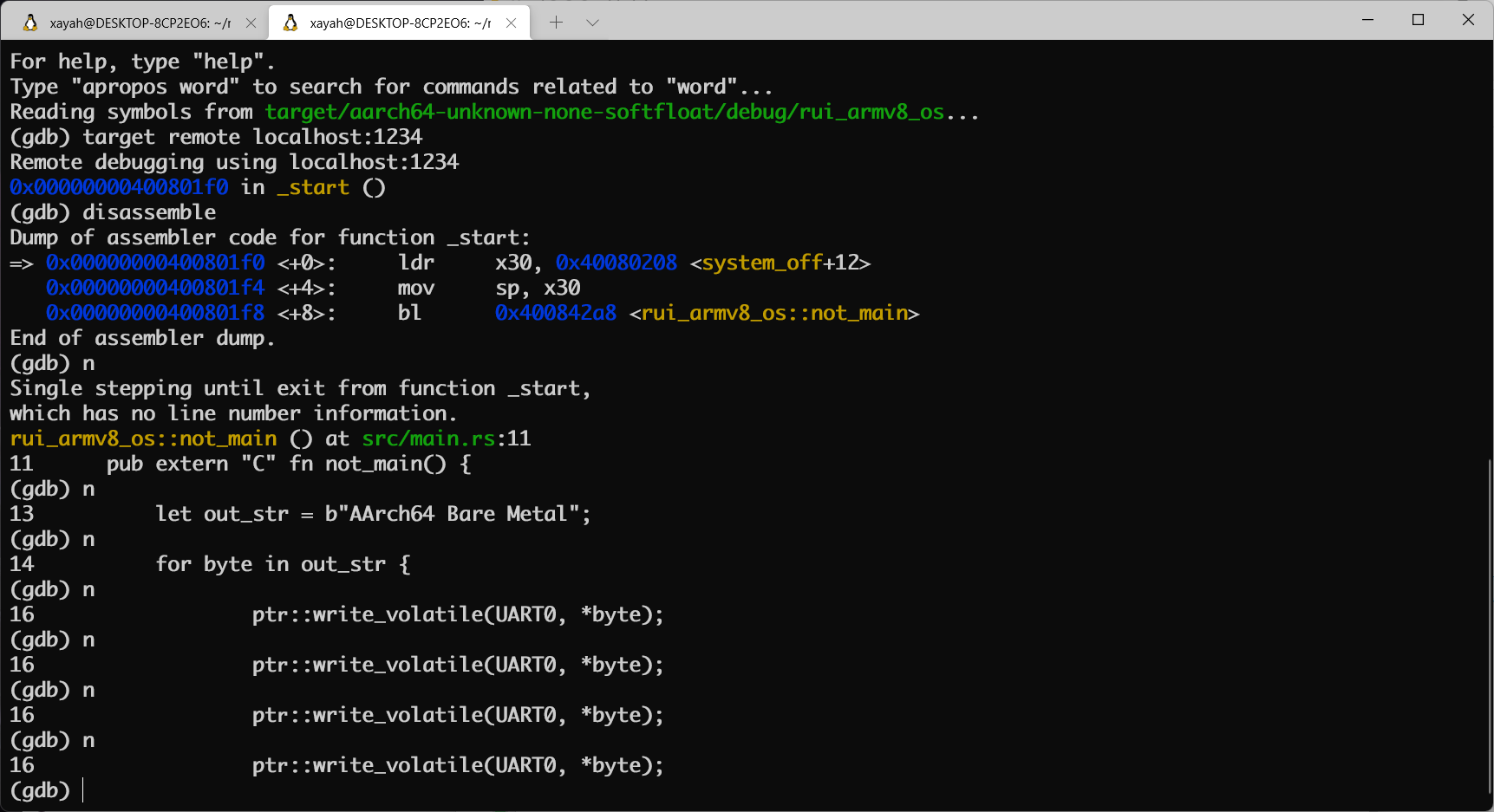
连接调试客户端
1 target remote localhost:1234
查看汇编码
单步运行
二、Hello World
参考代码:下载
print函数是学习几乎任何一种软件开发语言时最先 学习使用的函数,同时该函数也是最基本和原始的程序调试手段 ,但该函数的实现却并不简单 。本实验的目的在于理解操作系统与硬件的接口方法 ,并实现一个可打印字符的宏 (非系统调用 ),用于后续的调试 和开发 。
1. 了解virt机器
操作系统 介于硬件 和应用程序 之间,向下管理硬件资源 ,向上提供应用编程接口 。设计并实现操作系统 需要熟悉底层硬件 的组成 及其操作方法 。
本系列实验都会在QEMU模拟器 上完成,首先来了解一下模拟的机器信息 。可以通过下列两种方法 :
1) 文档或源码方式
查看QEMU 关于virt 的描述 , 或者查看QEMU 的源码 ,如GitHub 上的virt.h 和virt.c 。virt.c中可见如下有关内存映射 的内容。
1
2
3
4
5
6
7
8
9
10
11
12
13
14
15
16
17
18
19
20
21
22
23
24
25
26
27
28
29
30
31
32
33
34
35
36
37
38
39
40
41
42
43
44
45
46
47
/* Addresses and sizes of our components. * 0..128MB is space for a flash device so we can run bootrom code such as UEFI. * 128MB..256MB is used for miscellaneous device I/O. * 256MB..1GB is reserved for possible future PCI support (ie where the * PCI memory window will go if we add a PCI host controller). * 1GB and up is RAM (which may happily spill over into the * high memory region beyond 4GB). * This represents a compromise between how much RAM can be given to * a 32 bit VM and leaving space for expansion and in particular for PCI. * Note that devices should generally be placed at multiples of 0x10000, * to accommodate guests using 64K pages. */ static const MemMapEntry base_memmap[] = { /* Space up to 0x8000000 is reserved for a boot ROM */ [VIRT_FLASH] = { 0, 0x08000000 }, [VIRT_CPUPERIPHS] = { 0x08000000, 0x00020000 }, /* GIC distributor and CPU interfaces sit inside the CPU peripheral space */ [VIRT_GIC_DIST] = { 0x08000000, 0x00010000 }, [VIRT_GIC_CPU] = { 0x08010000, 0x00010000 }, [VIRT_GIC_V2M] = { 0x08020000, 0x00001000 }, [VIRT_GIC_HYP] = { 0x08030000, 0x00010000 }, [VIRT_GIC_VCPU] = { 0x08040000, 0x00010000 }, /* The space in between here is reserved for GICv3 CPU/vCPU/HYP */ [VIRT_GIC_ITS] = { 0x08080000, 0x00020000 }, /* This redistributor space allows up to 2*64kB*123 CPUs */ [VIRT_GIC_REDIST] = { 0x080A0000, 0x00F60000 }, [VIRT_UART] = { 0x09000000, 0x00001000 }, [VIRT_RTC] = { 0x09010000, 0x00001000 }, [VIRT_FW_CFG] = { 0x09020000, 0x00000018 }, [VIRT_GPIO] = { 0x09030000, 0x00001000 }, [VIRT_SECURE_UART] = { 0x09040000, 0x00001000 }, [VIRT_SMMU] = { 0x09050000, 0x00020000 }, [VIRT_PCDIMM_ACPI] = { 0x09070000, MEMORY_HOTPLUG_IO_LEN }, [VIRT_ACPI_GED] = { 0x09080000, ACPI_GED_EVT_SEL_LEN }, [VIRT_NVDIMM_ACPI] = { 0x09090000, NVDIMM_ACPI_IO_LEN}, [VIRT_PVTIME] = { 0x090a0000, 0x00010000 }, [VIRT_SECURE_GPIO] = { 0x090b0000, 0x00001000 }, [VIRT_MMIO] = { 0x0a000000, 0x00000200 }, /* ...repeating for a total of NUM_VIRTIO_TRANSPORTS, each of that size */ [VIRT_PLATFORM_BUS] = { 0x0c000000, 0x02000000 }, [VIRT_SECURE_MEM] = { 0x0e000000, 0x01000000 }, [VIRT_PCIE_MMIO] = { 0x10000000, 0x2eff0000 }, [VIRT_PCIE_PIO] = { 0x3eff0000, 0x00010000 }, [VIRT_PCIE_ECAM] = { 0x3f000000, 0x01000000 }, /* Actual RAM size depends on initial RAM and device memory settings */ [VIRT_MEM] = { GiB, LEGACY_RAMLIMIT_BYTES }, };
2) 设备树(Device Tree)方式 首先安装DTC
1 sudo apt-get install device-tree-compiler
新建一个设备树目录 并进入
1 mkdir ~/device && cd ~/device
导出DT
1 qemu-system-aarch64 -machine virt,dumpdtb=virt.dtb -cpu cortex-a53 -nographic
-machine virt指明机器类型 为virt ,这是QEMU 仿真的虚拟机器 。
用DTC 将导出的Device Tree Blob 转换为Device Tree Source
1 dtc -I dtb -O dts -o virt.dts virt.dtb
用文本编辑器 打开virt.dts,可以发现如下内容
1
2
3
4
5
6
7
8
9
10
11
pl011@9000000 { clock-names = "uartclk\0apb_pclk"; clocks = <0x8000 0x8000>; interrupts = <0x00 0x01 0x04>; reg = <0x00 0x9000000 0x00 0x1000>; compatible = "arm,pl011\0arm,primecell"; }; /* ······ */ chosen { stdout-path = "/pl011@9000000"; };
由上可以看出,virt 机器包含有pl011 的设备,该设备的寄存器 在0x9000000开始处。pl011 实际上是一个UART设备 ,即串口 。可以看到virt 选择使用pl011 作为标准输出 ,这是因为与PC不同 ,大部分嵌入式系统 默认情况下并不包含VGA设备 。
2. 实现println!宏
我们参照Writing an OS in Rust - VGA Text Mode (使用Rust编写操作系统(三):VGA字符模式 )来实现println!宏,但与之不同的是,我们使用串口 来输出,而不是通过操作VGA 的Frame Buffer 。
1) 用串口实现println!宏 进入rui_armv8_os目录
新建src/uart_console.rs
1 touch src/uart_console.rs
编辑src/uart_console.rs,定义一个Writer结构 ,实现字节写入 和字符串写入 。
1
2
3
4
5
6
7
8
9
10
11
12
13
14
15
16
17
18
//嵌入式系统使用串口,而不是vga,直接输出,没有颜色控制,不记录列号,也没有frame buffer,所以采用空结构 pub struct Writer; //往串口寄存器写入字节和字符串进行输出 impl Writer { pub fn write_byte(&mut self, byte: u8) { const UART0: *mut u8 = 0x0900_0000 as *mut u8; unsafe { ptr::write_volatile(UART0, byte); } } pub fn write_string(&mut self, s: &str) { for byte in s.chars() { self.write_byte(byte as u8) } } }
如何操作硬件通常需要阅读硬件制造商 提供的技术手册 。如pl011 串口设备(PrimeCell UART)是arm 设计的,其技术参考手册 可以通过其官网 查看。
依据之前virt.dts中的描述,pl011 的寄存器 在virt 机器中被映射 到了0x9000000的内存位置 。通过访问pl011 的技术参考手册 中Chapter 3. Programmers Model中的Summary of registers一节可知:第0号寄存器 是pl011 串口的数据寄存器 ,用于数据 的收发 。其详细描述 参见 这里 。
注意到我们只是向UART0 写入,而没从UART0 读出(如果读出会读出其他设备 通过串口 发送过来的数据,而不是 刚才写入 的数据,这与读写内存 时是不一样的,详情参见pl011 的技术手册 ),编译器 在优化 时可能对这部分代码进行错误 的优化 ,如把这些操作都忽略掉 。
使用ptr::write_volatile库的目的 是告诉编译器 ,这些写入 有特定目的 ,不应将其优化 (也就是告诉编译器不要瞎优化 ,这些写入 和读出 都有特定用途 。
比如连续两次读 ,编译器 可能认为第二次读 就是前次的值 ,所以优化 掉第二次读 ,但对外设寄存器 的连续读 可能返回不同的值 。
比如写,编译器 可能认为写 后没有读 所以写 没有作用,或者连续的写 会覆盖 前面的写 ,但对这些寄存器 的写入 对外设 都有特定作用 )。
在src/uart_console.rs中为Write结构 实现core::fmt::Writetrait ,该trait 会自动实现write_fmt方法,支持格式化 。
1
2
3
4
5
6
7
8
9
10
11
12
13
14
15
//嵌入式系统使用串口,而不是vga,直接输出,没有颜色控制,不记录列号,也没有frame buffer,所以采用空结构 pub struct Writer; //往串口寄存器写入字节和字符串进行输出 impl Writer { // ······ } impl core::fmt::Write for Writer { fn write_str(&mut self, s: &str) -> fmt::Result { self.write_string(s); Ok(()) } }
基于Rust 的core::fmt实现格式化控制 ,可以使我们方便地打印不同类型 的变量 。实现core::fmt::Write后,我们就可以使用Rust 内置的格式化 宏write!和writeln!,这使你瞬间具有其他语言 运行时所提供的格式化控制能力 。
2) 测试 在main.rs末尾加入以下代码
1
2
3
4
5
6
7
8
9
10
11
12
13
14
15
16
17
18
19
20
21
22
23
24
25
26
27
28
29
30
31
32
33
#![no_std] // 不使用标准库 #![no_main] // 不使用预定义入口点 // ······ #[no_mangle] // 不修改函数名 pub extern "C" fn not_main() { // ······ } include!("uart_console.rs"); use core::fmt; pub fn print_something() { // 一定要引用core::fmt::Write;否则报错:no method named `write_fmt` found for struct `Writer` in the current scope。 pub use core::fmt::Write; let mut writer = Writer {}; let display: fmt::Arguments = format_args!("hello arguments!\n"); writer.write_string("\n-----My writer-----\n"); writer.write_byte(b'H'); writer.write_string("ello "); writer.write_string("World!\n"); writer.write_string("[0] Hello from Rust!\n"); // 通过实现core::fmt::Write自动实现的方法 writer.write_fmt(display).unwrap(); // 使用write!宏 write!(writer, "The numbers are {} and {} \n", "42", "1.0").unwrap(); writer.write_string("-----My writer-----"); }
编辑main.rs中not_main函数:
1
2
3
4
pub extern "C" fn not_main() { // ······ print_something(); // 调用测试函数 }
编译 并运行
1 cargo build && qemu-system-aarch64 -machine virt -m 1024M -cpu cortex-a53 -nographic -kernel target/aarch64-unknown-none-softfloat/debug/rui_armv8_os
按住CTRL + A,然后松手按C,输入quit即可退出QEMU模拟器 。
3) 全局实现
现在我们已经可以采用print_something函数通过串口输出 字符了。但若要实现输出 ,我们需要两个 步骤:Writer类型 的实例 。实例 的write_byte或write_string等函数 。
为了方便在其他模块 中调用 ,我们希望可以直接执行步骤(2) 而不是先执行步骤(1) 再执行步骤(2) 。
一般情况下可以通过将步骤(1) 中的实例 定义为static类型来实现,但Rust 暂不支持Write r这样类型的静态(编译时)初始化 ,需要使用lazy_static来解决。此外,为了保证访问安全 还引入了自旋锁(spin) 。
编辑Cargo.toml:
1
2
3
4
5
6
7
8
9
10
11
12
# ······ # See more keys and their definitions at https://doc.rust-lang.org/cargo/reference/manifest.html [dependencies] spin = "0.9.2" [dependencies.lazy_static] version = "1.0" features = ["spin_no_std"] # eh_personality语言项标记的函数,将被用于实现栈展开(stack unwinding)。 # ······
编辑src/uart_console.rs,实现print!和println!宏。
1
2
3
4
5
6
7
8
9
10
11
12
13
14
15
16
17
18
19
20
21
22
23
24
25
26
27
28
29
30
31
32
33
34
35
36
impl core::fmt::Write for Writer { // ······ } use core::{fmt, ptr}; use lazy_static::lazy_static; use spin::Mutex; lazy_static! { /// A global `Writer` instance that can be used for printing to the VGA text buffer. /// /// Used by the `print!` and `println!` macros. pub static ref WRITER: Mutex<Writer> = Mutex::new(Writer { }); } /// Like the `print!` macro in the standard library, but prints to the VGA text buffer. #[macro_export] macro_rules! print { ($($arg:tt)*) => ($crate::uart_console::_print(format_args!($($arg)*))); } /// Like the `println!` macro in the standard library, but prints to the VGA text buffer. #[macro_export] macro_rules! println { () => ($crate::print!("\n")); ($($arg:tt)*) => ($crate::print!("{}\n", format_args!($($arg)*))); } /// Prints the given formatted string to the VGA text buffer through the global `WRITER` instance. #[doc(hidden)] pub fn _print(args: fmt::Arguments) { use core::fmt::Write; WRITER.lock().write_fmt(args).unwrap(); }
在main.rs中注释或删除之前的print_something()函数及其调用 ,测试println!宏
1
2
3
4
5
6
7
8
// ······ mod uart_console; // ······ pub extern "C" fn not_main() { // ······ println!("\n[0] Hello from Rust!"); }
编译 并运行
1 cargo build && qemu-system-aarch64 -machine virt -m 1024M -cpu cortex-a53 -nographic -kernel target/aarch64-unknown-none-softfloat/debug/rui_armv8_os
三、设备树(可选)
参考湖南大学2022年操作系统课程实验 - 实验三 设备树(可选)
四、中断
参考代码:下载
中断 、异常 和陷阱 指令是操作系统 的基石 ,现代操作系统就是由中断驱动 的。本实验的目的在于深刻理解中断的原理和机制 ,掌握CPU访问设备控制器的方法 ,掌握ARM体系结构的中断机制和规范 ,实现时钟中断服务和部分异常处理 等。
1. 概念 1) 陷入操作系统
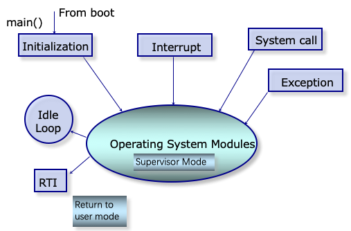
如下图所示,操作系统 是一个多入口 的程序 ,执行陷阱(Trap)指令 ,出现异常 、发生中断 时都会陷入 到操作系统 。
2) ARM的中断系统
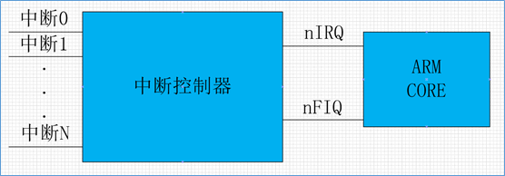
中断 是一种硬件机制 。借助于中断 ,CPU 可以不必再采用轮询 这种低效 的方式访问外部设备 。将所有的外部设备 与CPU直接相连 是不现实 的,外部设备 的中断请求 一般经由中断控制器 ,由中断控制器 仲裁后再转发给CPU 。如下图所示ARM 的中断系统 。
其中nIRQ 是普通中断 ,nFIQ 是快速中断 。ARM 采用的中断控制器 叫做GIC ,即General Interrupt Controller 。GIC 包括多个版本,如GICv1(已弃用) ,GICv2 ,GICv3 ,GICv4 。简单起见,我们实验将选用GICv2 版本。
为了配置好GICv2中断控制器 ,与pl011串口 一样,我们需要阅读其技术参考手册 。
访问ARM 官网下载ARM Generic Interrupt Controller Architecture version 2.0 - Architecture Specification 。
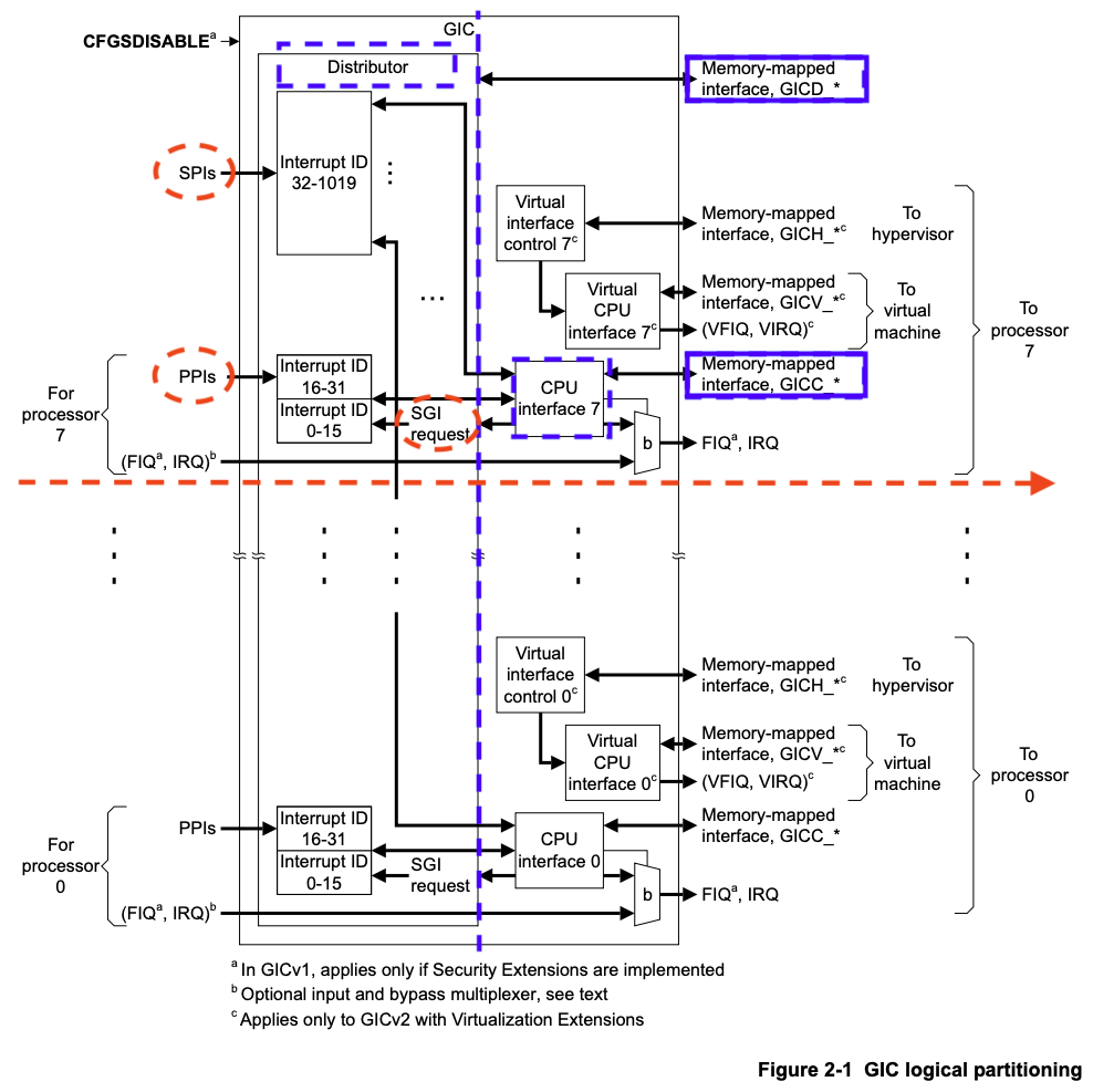
从上图(来源于ARM Generic Interrupt Controller Architecture version 2.0 - Architecture Specification 中的Chapter 2 GIC Partitioning )可以看出:
GICv2 最多支持8核 的中断管理 。GIC 包括两大主要部分 (由图中蓝色虚竖线 分隔,Distributor 和CPU Interface 由蓝色虚矩形框 标示),分别是:
Distributor ,其通过GICD_开头的寄存器进行控制(蓝色实矩形框 标示)CPU Interface ,其通过GICC_开头的寄存器进行控制(蓝色实矩形框 标示)
中断类型 分为以下几类(由图中红色虚线椭圆 标示):
SPI:(Shared Peripheral Interrupt) ,共享外设中断 。该中断 来源于外设 ,通过Distributor 分发给特定的Core ,其中断编号 为32-1019 。从图中可以看到所有核共享SPI 。PPI:(Private Peripheral Interrupt) ,私有外设中断 。该中断 来源于外设 ,但只对指定的Core 有效,中断信号 只会发送给指定的Core ,其中断编号 为16-31 。从图中可以看到每个Core 都有自己的PPI 。SGI:(Software-Generated Interrupt) ,软中断 。软件产生 的中断 ,用于给其他的Core 发送中断信号 ,其中断编号 为0-15 。Virtual Interrupt ,虚拟中断 ,用于支持虚拟机 。图中也可以看到,因为我们暂时不关心 ,所以没有标注。此外可以看到(FIQ,IRQ) 可通过b 进行旁路 ,我们也不关心。如感兴趣可以查看技术手册 了解细节。
此外,由ARM Generic Interrupt Controller Architecture version 2.0 - Architecture Specification (Section 1.4.2)可知,外设中断 可由两种方式 触发:
Edge-Triggered :边沿触发 ,当检测到中断信号上升沿 时中断有效 。Level-Sensitive :电平触发 ,当中断源 为指定电平 时中断有效 。SOC 中中断 有很多,为了方便对中断的管理 ,对每个中断 附加了中断优先级 。在中断仲裁 时,高优先级的中断 ,会优于低优先级的中断 ,发送给CPU处理 。当CPU 在响应低优先级中断 时,如果此时来了高优先级中断 ,那么高优先级中断 会抢占低优先级中断 ,而被处理器响应 。ARM Generic Interrupt Controller Architecture version 2.0 - Architecture Specification (Section 3.3)可知,GICv2 最多支持256 个中断优先级 。GICv2 中规定,所支持的中断优先级别数 与GIC 的具体实现有关,如果支持的中断优先级数 比256 少(最少为16 ),则8位优先级 的低位 为0 ,且遵循RAZ/WI(Read-As-Zero, Writes Ignored) 原则。
3) GICv2初始化 1 2 3 4 5 6 7 8 9 10 11 12 13 14 15 16 17 18 19 20 21 22 23 24 /* ······ */ intc@8000000 { phandle = <0x8001>; reg = <0x00 0x8000000 0x00 0x10000 0x00 0x8010000 0x00 0x10000>; compatible = "arm,cortex-a15-gic"; ranges; #size-cells = <0x02>; #address-cells = <0x02>; interrupt-controller; #interrupt-cells = <0x03>; v2m@8020000 { phandle = <0x8002>; reg = <0x00 0x8020000 0x00 0x1000>; msi-controller; compatible = "arm,gic-v2m-frame"; }; }; /* ······ */ timer { interrupts = <0x01 0x0d 0x104 0x01 0x0e 0x104 0x01 0x0b 0x104 0x01 0x0a 0x104>; always-on; compatible = "arm,armv8-timer\0arm,armv7-timer"; };
由virt.dts中intc和timer的部分并结合kernel.org 中关于ARM Generic Interrupt Controller 和ARM architected timer 的DeviceTree 的说明可知:
intc中的reg指明GICD寄存器 映射到内存的位置为0x8000000,长度为0x10000,GICC寄存器 映射到内存的位置为0x8010000,长度为0x10000。intc中的#interrupt-cells指明interrupts 包括3 个cells 。第一个文档 指明:第一个cell 为中断类型 ,0 表示SPI ,1 表示PPI ;第二个cell 为中断号 ,SPI 范围为**[0-987], PPI为 [0-15];第三个 cell为 flags,其中 [3:0]位表示 触发类型, [4]表示 高电平触发, [15:8]为 PPI的 CPU中断掩码,每 1位对应一个 CPU,为 1表示该 中断会连接到对应的 CPU**。以timer设备为例,其中包括4 个中断 。以第2 个中断 的参数0x01 0x0e 0x104为例,其指明该中断 为PPI 类型的中断 ,中断号14 , 路由到第一个CPU ,且高电平触发 。但注意到PPI 的起始中断号 为16 ,所以实际上该中断 在GICv2 中的中断号 应为16 + 14 = 30 。ARM Generic Interrupt Controller Architecture version 2.0 - Architecture Specification ,在Chapter 4 Programmers’ Model 部分有关于GICD 和GICC寄存器 的描述,以及如何使能 Distributor和 CPU Interfaces**的方法。
4) ARMv8的中断与异常处理
访问ARM官网 下载并阅读ARM Cortex-A Series Programmer’s Guide for ARMv8-A 和AArch64 Exception and Interrupt Handling 等技术参考手册 。ARMv8架构 定义了两种执行状态(Execution States ): AArch64 和AArch32 。分别对应使用64位宽通用寄存器 或32位宽通用寄存器 的执行。
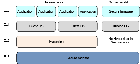
上图所示为AArch64 中的异常级别(Exception levels)的组织。可见 AArch64 中共有4 个异常级别 ,分别为EL0 ,EL1 ,EL2 和EL3 。在AArch64 中,Interrupt 是Exception 的子类型 ,称为异常 。AArch64 中有四种类型 的异常 :
Sync(Synchronous exceptions,同步异常) 。在执行时触发 的异常 ,例如在尝试访问不存在 的内存地址 时。IRQ (Interrupt requests,中断请求) 。由外部设备 产生的中断 。FIQ (Fast Interrupt Requests,快速中断请求) 。类似于IRQ ,但具有更高 的优先级 ,因此FIQ 中断服务程序不能被其他IRQ 或FIQ 中断。SError (System Error,系统错误) 。用于外部数据 中止的异步中断 。异常 发生时,处理器 将执行与该异常 对应的异常处理代码 。在ARM架构 中,这些异常处理代码 将会被保存在内存 的异常向量表 中。每一个异常级别(EL0,EL1,EL2和EL3) 都有其对应的异常向量表 。需要注意的是,与x86等架构 不同,该表包含的是要执行的指令 ,而不是函数地址 。
异常向量表 的基地址 由VBAR_ELn给出,然后每个表项都有一个从该基地址 定义的偏移量 。 每个表有16 个表项,每个表项的大小为128(0x80) 字节(32 条指令 )。 该表实际上有4 组,每组4 个表项。 分别是:
发生于当前异常级别 的异常 且SPSel寄存器 选择SP0 ,Sync 、IRQ 、FIQ 、SError 对应的4个异常处理 。
发生于当前异常级别 的异常 且SPSel寄存器 选择SPx ,Sync 、IRQ 、FIQ 、SError 对应的4个异常处理 。
发生于较低异常级别 的异常 且执行状态 为AArch64 ,Sync 、IRQ 、FIQ 、SError 对应的4个异常处理 。
发生于较低异常级别 的异常 且执行状态 为AArch32 ,Sync 、IRQ 、FIQ 、SError 对应的4个异常处理 。
2. 实现 1) 编写代码 新建src/interrupts.rs,src/exceptions.s
1 touch src/interrupts.rs src/exceptions.s
编辑src/interrupts.rs,定义各种常量 ,如寄存器地址 和寄存器值 等,然后定义init_gicv2函数对GICD 和GICC 进行初始化 ,最后定义若干辅助函数 用于中断配置 。
1 2 3 4 5 6 7 8 9 10 11 12 13 14 15 16 17 18 19 20 21 22 23 24 25 26 27 28 29 30 31 32 33 34 35 36 37 38 39 40 41 42 43 44 45 46 47 48 49 50 51 52 53 54 55 56 57 58 59 60 61 62 63 64 65 66 67 68 69 70 71 72 73 74 75 76 77 78 79 80 81 82 83 84 85 86 87 88 89 90 91 92 93 94 95 96 97 98 99 100 101 102 103 104 105 106 107 108 109 110 use core::ptr; // GICD和GICC寄存器内存映射后的起始地址 const GICD_BASE: u64 = 0x08000000; const GICC_BASE: u64 = 0x08010000; // Distributor const GICD_CTLR: *mut u32 = (GICD_BASE + 0x0) as *mut u32; const GICD_ISENABLER: *mut u32 = (GICD_BASE + 0x0100) as *mut u32; const GICD_ICENABLER: *mut u32 = (GICD_BASE + 0x0180) as *mut u32; const GICD_ICPENDR: *mut u32 = (GICD_BASE + 0x0280) as *mut u32; const GICD_IPRIORITYR: *mut u32 = (GICD_BASE + 0x0400) as *mut u32; const GICD_ICFGR: *mut u32 = (GICD_BASE + 0x0c00) as *mut u32; const GICD_CTLR_ENABLE: u32 = 1; /* Enable GICD */ const GICD_CTLR_DISABLE: u32 = 0; /* Disable GICD */ const GICD_ISENABLER_SIZE: u32 = 32; const GICD_ICENABLER_SIZE: u32 = 32; const GICD_ICPENDR_SIZE: u32 = 32; const GICD_IPRIORITY_SIZE: u32 = 4; const GICD_IPRIORITY_BITS: u32 = 8; const GICD_ICFGR_SIZE: u32 = 16; const GICD_ICFGR_BITS: u32 = 2; // CPU Interface const GICC_CTLR: *mut u32 = (GICC_BASE + 0x0) as *mut u32; const GICC_PMR: *mut u32 = (GICC_BASE + 0x0004) as *mut u32; const GICC_BPR: *mut u32 = (GICC_BASE + 0x0008) as *mut u32; const GICC_CTLR_ENABLE: u32 = 1; const GICC_CTLR_DISABLE: u32 = 0; // Priority Mask Register. interrupt priority filter, Higher priority corresponds to a lower Priority field value. const GICC_PMR_PRIO_LOW: u32 = 0xff; // The register defines the point at which the priority value fields split into two parts, // the group priority field and the subpriority field. The group priority field is used to // determine interrupt preemption. NO GROUP. const GICC_BPR_NO_GROUP: u32 = 0x00; pub fn init_gicv2() { // 初始化Gicv2的distributor和cpu interface // 禁用distributor和cpu interface后进行相应配置 unsafe { ptr::write_volatile(GICD_CTLR, GICD_CTLR_DISABLE); ptr::write_volatile(GICC_CTLR, GICC_CTLR_DISABLE); ptr::write_volatile(GICC_PMR, GICC_PMR_PRIO_LOW); ptr::write_volatile(GICC_BPR, GICC_BPR_NO_GROUP); } // 启用distributor和cpu interface unsafe { ptr::write_volatile(GICD_CTLR, GICD_CTLR_ENABLE); ptr::write_volatile(GICC_CTLR, GICC_CTLR_ENABLE); } } // 使能中断号为interrupt的中断 pub fn enable(interrupt: u32) { unsafe { ptr::write_volatile( GICD_ISENABLER.add((interrupt / GICD_ISENABLER_SIZE) as usize), 1 << (interrupt % GICD_ISENABLER_SIZE) ); } } // 禁用中断号为interrupt的中断 pub fn disable(interrupt: u32) { unsafe { ptr::write_volatile( GICD_ICENABLER.add((interrupt / GICD_ICENABLER_SIZE) as usize), 1 << (interrupt % GICD_ICENABLER_SIZE) ); } } // 清除中断号为interrupt的中断 pub fn clear(interrupt: u32) { unsafe { ptr::write_volatile( GICD_ICPENDR.add((interrupt / GICD_ICPENDR_SIZE) as usize), 1 << (interrupt % GICD_ICPENDR_SIZE) ); } } // 设置中断号为interrupt的中断的优先级为priority pub fn set_priority(interrupt: u32, priority: u32) { let shift = (interrupt % GICD_IPRIORITY_SIZE) * GICD_IPRIORITY_BITS; unsafe { let addr: *mut u32 = GICD_IPRIORITYR.add((interrupt / GICD_IPRIORITY_SIZE) as usize); let mut value: u32 = ptr::read_volatile(addr); value &= !(0xff << shift); value |= priority << shift; ptr::write_volatile(addr, value); } } // 设置中断号为interrupt的中断的属性为config pub fn set_config(interrupt: u32, config: u32) { let shift = (interrupt % GICD_ICFGR_SIZE) * GICD_ICFGR_BITS; unsafe { let addr: *mut u32 = GICD_ICFGR.add((interrupt / GICD_ICFGR_SIZE) as usize); let mut value: u32 = ptr::read_volatile(addr); value &= !(0x03 << shift); value |= config << shift; ptr::write_volatile(addr, value); } }
编辑src/exceptions.s,参照AArch64 exception table 定义异常向量表。
1 2 3 4 5 6 7 8 9 10 11 12 13 14 15 16 17 18 19 20 21 22 23 24 25 26 27 28 29 30 31 32 33 34 35 36 37 38 39 40 41 42 43 44 45 46 47 48 49 50 51 52 53 54 55 56 57 58 59 60 61 62 63 64 65 66 67 68 69 70 71 72 73 74 75 76 77 78 79 80 81 82 83 84 85 86 87 88 89 90 91 92 93 94 95 96 97 98 99 100 101 102 103 104 105 106 107 108 109 110 111 112 113 114 115 116 117 118 119 120 121 122 123 124 125 126 127 128 129 130 131 132 133 134 135 136 137 138 139 140 141 142 143 144 145 146 147 148 149 150 151 152 153 154 155 156 157 158 159 160 161 162 163 164 165 166 167 168 169 170 171 172 173 174 175 176 177 178 179 180 181 182 183 184 185 // SPDX-License-Identifier: MIT OR Apache-2.0 // // Copyright (c) 2018-2021 Andre Richter <andre.o.richter@gmail.com> .extern el1_sp0_sync .extern el1_sp0_irq .extern el1_sp0_fiq .extern el1_sp0_error .extern el1_sync .extern el1_irq .extern el1_fiq .extern el1_error .extern el0_sync .extern el0_irq .extern el0_fiq .extern el0_error .extern el0_32_sync .extern el0_32_irq .extern el0_32_fiq .extern el0_32_error //-------------------------------------------------------------------------------------------------- // Definitions //-------------------------------------------------------------------------------------------------- /// Call the function provided by parameter `\handler` after saving the exception context. Provide /// the context as the first parameter to '\handler'. .equ CONTEXT_SIZE, 264 .section .text.exceptions .macro EXCEPTION_VECTOR handler sub sp, sp, #CONTEXT_SIZE // store general purpose registers stp x0, x1, [sp, #16 * 0] stp x2, x3, [sp, #16 * 1] stp x4, x5, [sp, #16 * 2] stp x6, x7, [sp, #16 * 3] stp x8, x9, [sp, #16 * 4] stp x10, x11, [sp, #16 * 5] stp x12, x13, [sp, #16 * 6] stp x14, x15, [sp, #16 * 7] stp x16, x17, [sp, #16 * 8] stp x18, x19, [sp, #16 * 9] stp x20, x21, [sp, #16 * 10] stp x22, x23, [sp, #16 * 11] stp x24, x25, [sp, #16 * 12] stp x26, x27, [sp, #16 * 13] stp x28, x29, [sp, #16 * 14] // store exception link register and saved processor state register mrs x0, elr_el1 mrs x1, spsr_el1 stp x0, x1, [sp, #16 * 15] // store link register which is x30 str x30, [sp, #16 * 16] mov x0, sp // call exception handler bl \handler // exit exception b .exit_exception .endm //-------------------------------------------------------------------------------------------------- // Private Code //-------------------------------------------------------------------------------------------------- //------------------------------------------------------------------------------ // The exception vector table. //------------------------------------------------------------------------------ /** When an exception occurs, the processor must execute handler code that corresponds to the exception. The location in memory where the handler is stored is called the exception vector. In the ARM architecture, exception vectors are stored in a table, called the exception vector table. Each Exception level has its own vector table, that is, there is one for each of EL3, EL2, and EL1. The table contains instructions to be executed, rather than a set of addresses. These would normally be branch instructions that direct the core to the full exception handler. The exception vector table for EL1, for example, holds instructions for handling all types of exception that can occur at EL1, Vectors for individual exceptions are at fixed offsets from the beginning of the table. The virtual address of each table base is set by the Vector Based Address Registers: VBAR_EL3, VBAR_EL2 and VBAR_EL1. Each entry in the vector table is 16 instructions long (in ARMv7-A and AArch32, each entry is only 4 bytes). This means that in AArch64 the top-level handler can be written directly in the vector table. The base address is given by VBAR_ELn and each entry has a defined offset from this base address. Each table has 16 entries, with each entry being 128 bytes (32 instructions) in size. The table effectively consists of 4 sets of 4 entries. Which entry is used depends on several factors: The type of exception (SError, FIQ, IRQ, or Synchronous) If the exception is being taken at the same Exception level, the stack pointer to be used (SP0 or SPn) If the exception is being taken at a lower Exception level, the Execution state of the next lower level (AArch64 or AArch32). */ .section .text.exceptions_vector_table // Export a symbol for the Rust code to use. .globl exception_vector_table exception_vector_table: .org 0x0000 EXCEPTION_VECTOR el1_sp0_sync .org 0x0080 EXCEPTION_VECTOR el1_sp0_irq .org 0x0100 EXCEPTION_VECTOR el1_sp0_fiq .org 0x0180 EXCEPTION_VECTOR el1_sp0_error .org 0x0200 EXCEPTION_VECTOR el1_sync .org 0x0280 EXCEPTION_VECTOR el1_irq .org 0x0300 EXCEPTION_VECTOR el1_fiq .org 0x0380 EXCEPTION_VECTOR el1_error .org 0x0400 EXCEPTION_VECTOR el0_sync .org 0x0480 EXCEPTION_VECTOR el0_irq .org 0x0500 EXCEPTION_VECTOR el0_fiq .org 0x0580 EXCEPTION_VECTOR el0_error .org 0x0600 EXCEPTION_VECTOR el0_32_sync .org 0x0680 EXCEPTION_VECTOR el0_32_irq .org 0x0700 EXCEPTION_VECTOR el0_32_fiq .org 0x0780 EXCEPTION_VECTOR el0_32_error .org 0x0800 .exit_exception: // restore link register ldr x30, [sp, #16 * 16] // restore exception link register and saved processor state register ldp x0, x1, [sp, #16 * 15] msr elr_el1, x0 msr spsr_el1, x1 // restore general purpose registers ldp x28, x29, [sp, #16 * 14] ldp x26, x27, [sp, #16 * 13] ldp x24, x25, [sp, #16 * 12] ldp x22, x23, [sp, #16 * 11] ldp x20, x21, [sp, #16 * 10] ldp x18, x19, [sp, #16 * 9] ldp x16, x17, [sp, #16 * 8] ldp x14, x15, [sp, #16 * 7] ldp x12, x13, [sp, #16 * 6] ldp x10, x11, [sp, #16 * 5] ldp x8, x9, [sp, #16 * 4] ldp x6, x7, [sp, #16 * 3] ldp x4, x5, [sp, #16 * 2] ldp x2, x3, [sp, #16 * 1] ldp x0, x1, [sp, #16 * 0] // restore stack pointer add sp, sp, #CONTEXT_SIZE eret
编辑src/interrupts.rs,文末引入exceptions.s,同时定义结构ExceptionCtx,与src/exceptions.s中EXCEPTION_VECTOR宏保存的寄存器数据 对应。
1
2
3
4
5
6
7
8
9
10
11
12
// ······ // 注意:这里的······代表承接并省略上文代码 use core::arch::global_asm; global_asm!(include_str!("exceptions.s")); #[repr(C)] pub struct ExceptionCtx { regs: [u64; 30], elr_el1: u64, spsr_el1: u64, lr: u64, }
继续编辑src/interrupts.rs,在EXCEPTION_VECTOR宏中,每一类中断 都对应一个处理函数 。
1
2
3
4
5
6
7
8
9
10
11
12
13
14
15
16
17
18
19
20
21
22
23
24
25
26
27
28
29
30
31
32
33
34
35
36
37
38
39
40
41
42
43
44
45
46
47
48
49
50
51
52
53
54
55
56
57
58
59
60
61
62
63
64
65
66
67
68
69
70
71
72
73
74
75
76
77
78
79
80
81
82
83
84
85
86
87
88
89
90
91
92
93
94
95
96
97
98
99
100
101
102
103
104
105
106
107
// ······ const EL1_SP0_SYNC: &'static str = "EL1_SP0_SYNC"; const EL1_SP0_IRQ: &'static str = "EL1_SP0_IRQ"; const EL1_SP0_FIQ: &'static str = "EL1_SP0_FIQ"; const EL1_SP0_ERROR: &'static str = "EL1_SP0_ERROR"; const EL1_SYNC: &'static str = "EL1_SYNC"; const EL1_IRQ: &'static str = "EL1_IRQ"; const EL1_FIQ: &'static str = "EL1_FIQ"; const EL1_ERROR: &'static str = "EL1_ERROR"; const EL0_SYNC: &'static str = "EL0_SYNC"; const EL0_IRQ: &'static str = "EL0_IRQ"; const EL0_FIQ: &'static str = "EL0_FIQ"; const EL0_ERROR: &'static str = "EL0_ERROR"; const EL0_32_SYNC: &'static str = "EL0_32_SYNC"; const EL0_32_IRQ: &'static str = "EL0_32_IRQ"; const EL0_32_FIQ: &'static str = "EL0_32_FIQ"; const EL0_32_ERROR: &'static str = "EL0_32_ERROR"; // 调用我们的print!宏打印异常信息,你也可以选择打印异常发生时所有寄存器的信息 fn catch(ctx: &mut ExceptionCtx, name: &str) { crate::print!( "\n \ {} @ 0x{:016x}\n\n ", name, ctx.elr_el1, ); } #[no_mangle] unsafe extern "C" fn el1_sp0_sync(ctx: &mut ExceptionCtx) { catch(ctx, EL1_SP0_SYNC); } #[no_mangle] unsafe extern "C" fn el1_sp0_irq(ctx: &mut ExceptionCtx) { catch(ctx, EL1_SP0_IRQ); } #[no_mangle] unsafe extern "C" fn el1_sp0_fiq(ctx: &mut ExceptionCtx) { catch(ctx, EL1_SP0_FIQ); } #[no_mangle] unsafe extern "C" fn el1_sp0_error(ctx: &mut ExceptionCtx) { catch(ctx, EL1_SP0_ERROR); } #[no_mangle] unsafe extern "C" fn el1_sync(ctx: &mut ExceptionCtx) { catch(ctx, EL1_SYNC); } #[no_mangle] unsafe extern "C" fn el1_irq(ctx: &mut ExceptionCtx) { catch(ctx, EL1_IRQ); } #[no_mangle] unsafe extern "C" fn el1_fiq(ctx: &mut ExceptionCtx) { catch(ctx, EL1_FIQ); } #[no_mangle] unsafe extern "C" fn el1_error(ctx: &mut ExceptionCtx) { catch(ctx, EL1_ERROR); } #[no_mangle] unsafe extern "C" fn el0_sync(ctx: &mut ExceptionCtx) { catch(ctx, EL0_SYNC); } #[no_mangle] unsafe extern "C" fn el0_irq(ctx: &mut ExceptionCtx) { catch(ctx, EL0_IRQ); } #[no_mangle] unsafe extern "C" fn el0_fiq(ctx: &mut ExceptionCtx) { catch(ctx, EL0_FIQ); } #[no_mangle] unsafe extern "C" fn el0_error(ctx: &mut ExceptionCtx) { catch(ctx, EL0_ERROR); } #[no_mangle] unsafe extern "C" fn el0_32_sync(ctx: &mut ExceptionCtx) { catch(ctx, EL0_32_SYNC); } #[no_mangle] unsafe extern "C" fn el0_32_irq(ctx: &mut ExceptionCtx) { catch(ctx, EL0_32_IRQ); } #[no_mangle] unsafe extern "C" fn el0_32_fiq(ctx: &mut ExceptionCtx) { catch(ctx, EL0_32_FIQ); } #[no_mangle] unsafe extern "C" fn el0_32_error(ctx: &mut ExceptionCtx) { catch(ctx, EL0_32_ERROR); }
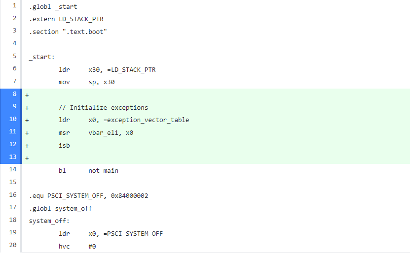
编辑src/start.s,载入异常向量表 exception_vector_table
1
2
3
4
5
6
7
8
9
10
// ······ mov sp, x30 // Initialize exceptions ldr x0, =exception_vector_table msr vbar_el1, x0 isb bl not_main // ······
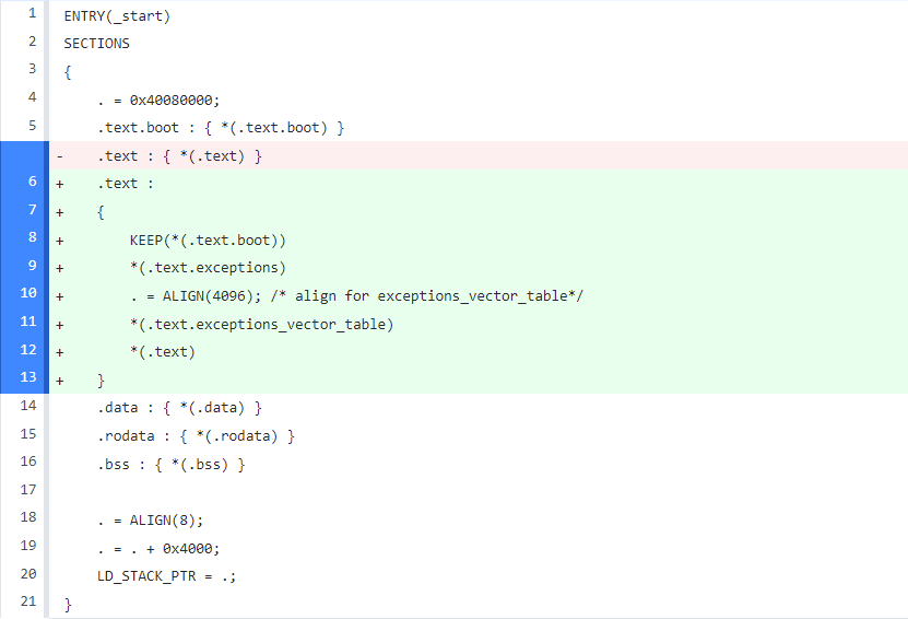
编辑aarch64-qemu.ld,处理链接脚本,为exceptions.s中定义的exceptions_vector_table选择位置,同时满足4K对齐 。
1
2
3
4
5
6
7
8
9
10
11
12
// ······ .text.boot : { *(.text.boot) } .text : { KEEP(*(.text.boot)) *(.text.exceptions) . = ALIGN(4096); /* align for exceptions_vector_table*/ *(.text.exceptions_vector_table) *(.text) } .data : { *(.data) } // ······
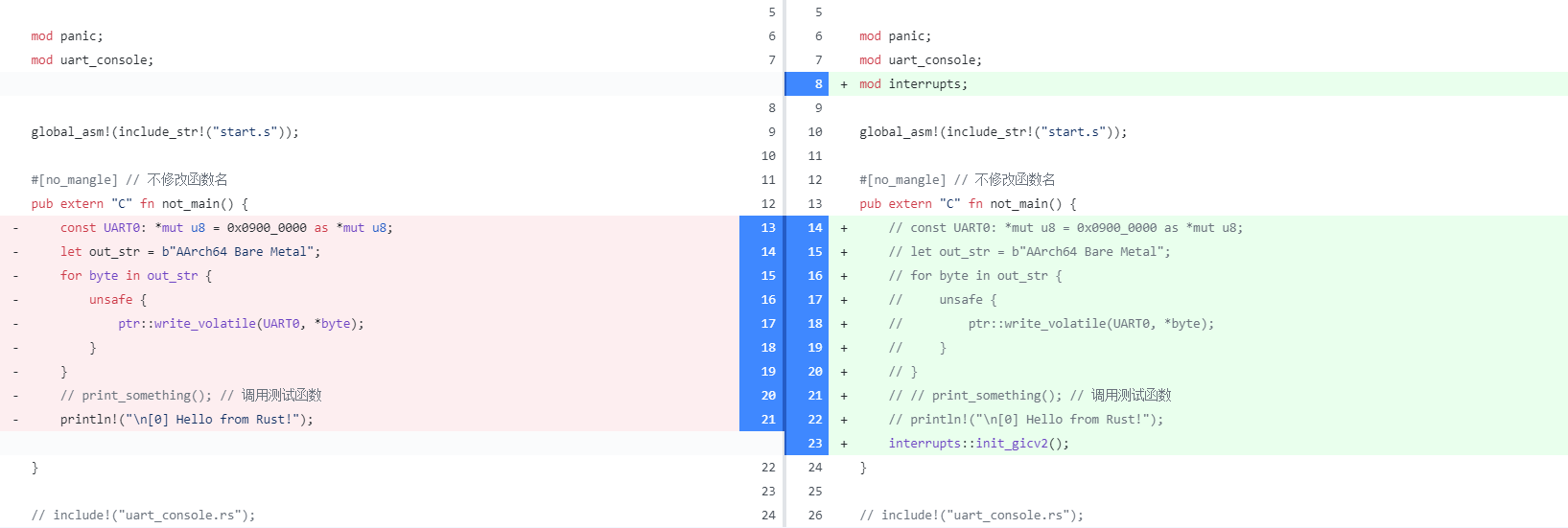
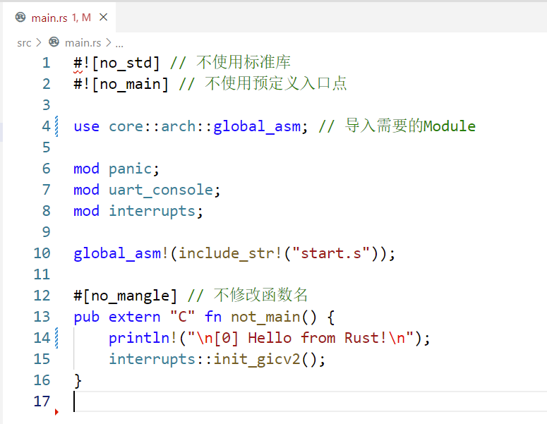
编辑src/main.rs,引入interrupts.rs模块,并在not_main()函数中注释掉之前的输出代码,调用init_gicv2()函数
1
2
3
4
5
6
7
8
9
10
11
12
13
14
15
16
17
18
19
20
21
// ······ mod panic; mod uart_console; mod interrupts; global_asm!(include_str!("start.s")); // ······ #[no_mangle] // 不修改函数名 pub extern "C" fn not_main() { // const UART0: *mut u8 = 0x0900_0000 as *mut u8; // let out_str = b"AArch64 Bare Metal"; // for byte in out_str { // unsafe { // ptr::write_volatile(UART0, *byte); // } // } // // print_something(); // 调用测试函数 // println!("\n[0] Hello from Rust!"); interrupts::init_gicv2(); } // ······
至此,我们已经在EL1级别 定义了完整的中断处理框架 ,可以开始处理实际的中断 了。
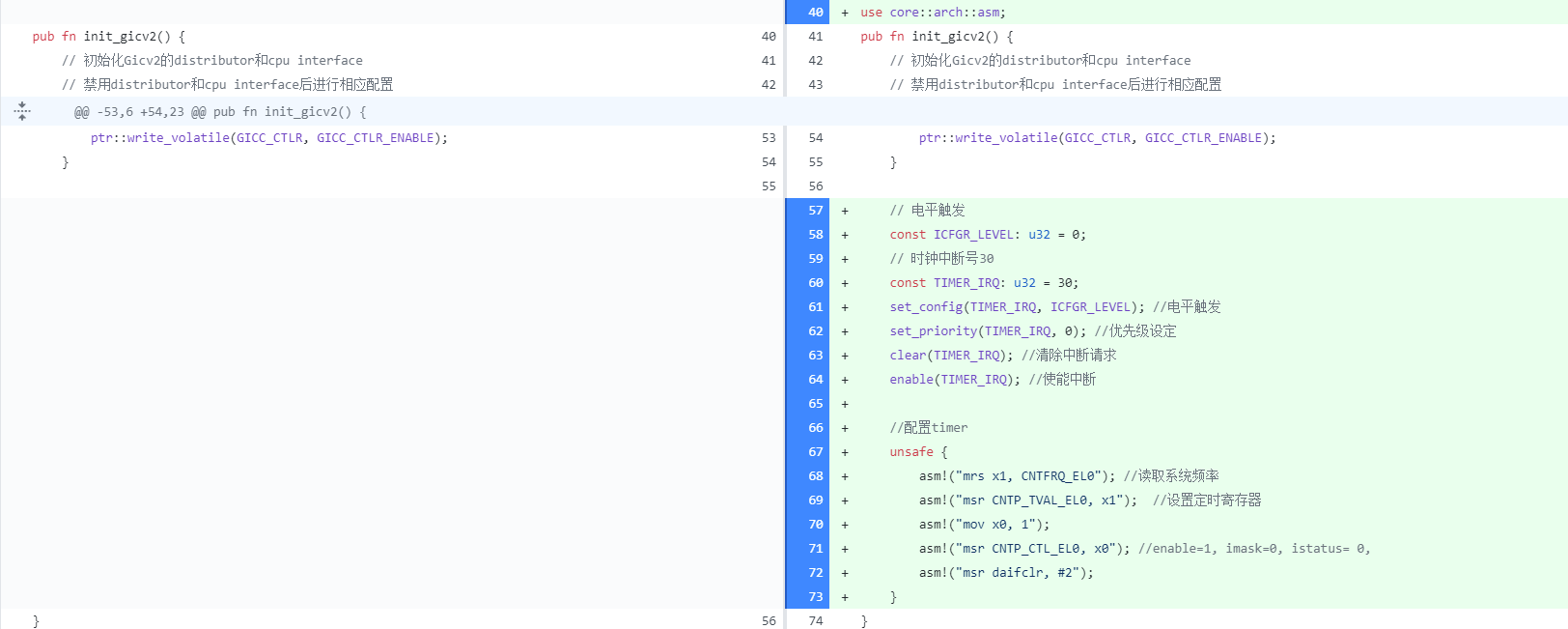
2) 使能时钟中断 编辑src/interrupts.rs,在init_gicv2函数中添加使能时钟中断 ,同时配置时钟 每秒产生一次中断 。
1
2
3
4
5
6
7
8
9
10
11
12
13
14
15
16
17
18
19
20
21
22
23
24
25
26
27
28
29
// ······ use core::arch::asm; pub fn init_gicv2() { // ······ // 启用distributor和cpu interface unsafe { ptr::write_volatile(GICD_CTLR, GICD_CTLR_ENABLE); ptr::write_volatile(GICC_CTLR, GICC_CTLR_ENABLE); } // 电平触发 const ICFGR_LEVEL: u32 = 0; // 时钟中断号30 const TIMER_IRQ: u32 = 30; set_config(TIMER_IRQ, ICFGR_LEVEL); // 电平触发 set_priority(TIMER_IRQ, 0); // 优先级设定 clear(TIMER_IRQ); // 清除中断请求 enable(TIMER_IRQ); // 使能中断 //配置timer unsafe { asm!("mrs x1, CNTFRQ_EL0"); // 读取系统频率 asm!("msr CNTP_TVAL_EL0, x1"); // 设置定时寄存器 asm!("mov x0, 1"); asm!("msr CNTP_CTL_EL0, x0"); // enable=1, imask=0, istatus= 0, asm!("msr daifclr, #2"); } } // ······
3) 调试 编译 并以调试模式 运行
1 cargo build && qemu-system-aarch64 -machine virt -m 1024M -cpu cortex-a53 -nographic -kernel target/aarch64-unknown-none-softfloat/debug/rui_armv8_os -S -s
保持 此终端会话 ,新开一个终端 ,配置GDB环境
1
2
3
4
cd ~/ToolChain/gcc-arm-10.3-2021.07-x86_64-aarch64-none-elf/bin export ToolChainPath=`pwd` cd ~/rui_armv8_os export PATH=$ToolChainPath:$PATH
启动GDB调试客户端
1 aarch64-none-elf-gdb target/aarch64-unknown-none-softfloat/debug/rui_armv8_os
连接远程客户端
1 target remote localhost:1234
在not_main()函数处设置断点
运行到interrupts::init_gicv2();语句之前。
我们之前在init_gicv2()函数中加入了以下代码
1
2
3
4
5
6
7
8
// 电平触发 const ICFGR_LEVEL: u32 = 0; // 时钟中断号30 const TIMER_IRQ: u32 = 30; set_config(TIMER_IRQ, ICFGR_LEVEL); //电平触发 set_priority(TIMER_IRQ, 0); //优先级设定 clear(TIMER_IRQ); //清除中断请求 enable(TIMER_IRQ); //使能中断
因此,当我们运行init_gicv2()函数后,其中的enable(TIMER_IRQ);会产生使能中断 。我们查看enable()函数的代码
1
2
3
4
5
6
7
8
9
// 使能中断号为interrupt的中断 pub fn enable(interrupt: u32) { unsafe { ptr::write_volatile( GICD_ISENABLER.add((interrupt / GICD_ISENABLER_SIZE) as usize), 1 << (interrupt % GICD_ISENABLER_SIZE) ); } }
由此可知,该函数对GICD_ISENABLER + interrupt / GICD_ISENABLER_SIZE对应的地址易失性 写入1 << (interrupt % GICD_ISENABLER_SIZE)。
我们之前在src/interrupts.rs中定义GICD寄存器内存映射GICD_BASE的起始地址为0x08000000,而GICD_ISENABLER的地址为GICD_BASE + 0x0100 = 0x08000100,GICD_ISENABLER_SIZE为32,TIMER_IRQ为30。
1
2
3
4
const GICD_BASE: u64 = 0x08000000; const GICD_ISENABLER: *mut u32 = (GICD_BASE + 0x0100) as *mut u32; const GICD_ISENABLER_SIZE: u32 = 32; const TIMER_IRQ: u32 = 30;
因此,对于enable(TIMER_IRQ);,我们可以理解为在0x08000100中易失性 写入1左移30位 后的二进制数 。
查看0x08000100地址中的值
我们得到了0000000000000000111111111111111,继续运行,执行interrupts::init_gicv2();,再次查看0x08000100地址中的值,此时变为了0100000000000000111111111111111
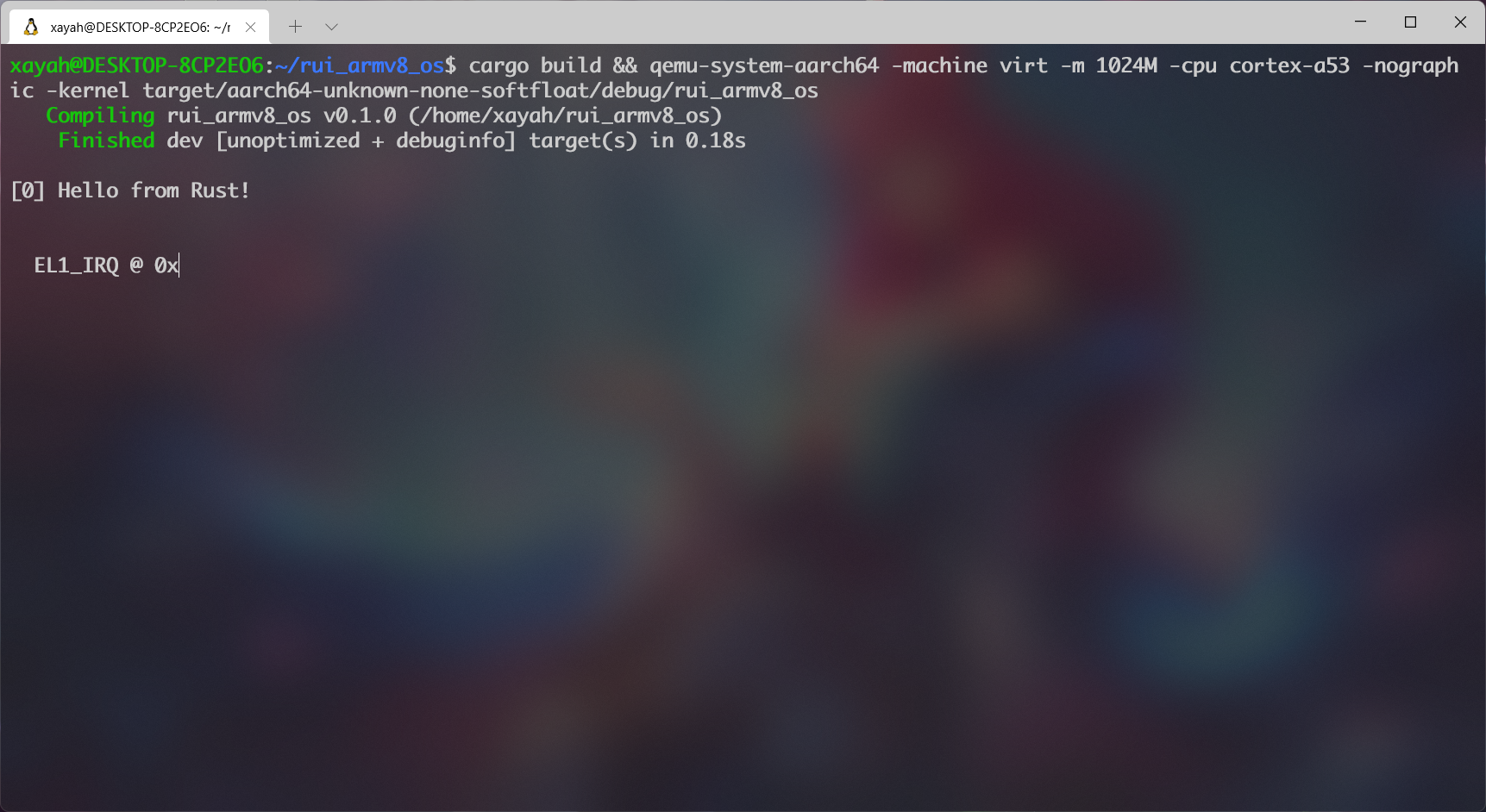
由此证明中断 产生了。并没有产生中断 !我们只是初始化 了GICV2 并且写入TIMER_IRQ中断号 ,如果时钟中断 生效了,那么理论上来说每隔一秒 都会调用一次 el1_irq()回调函数并且打印相应的中断信息 ,哪里出问题了呢?
四*、实现真正的时钟中断 1. 整理代码
参考代码:下载
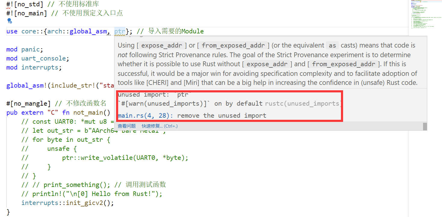
在实现真正的时钟中断 之前,我们的代码 已经有亿 点乱了,并且还会有很多恼人 的unused warnings ,因此我们先整理 一下代码 。src/main.rs:
注意到这里的core::ptr并没有被使用。
因此我们将其移除 。
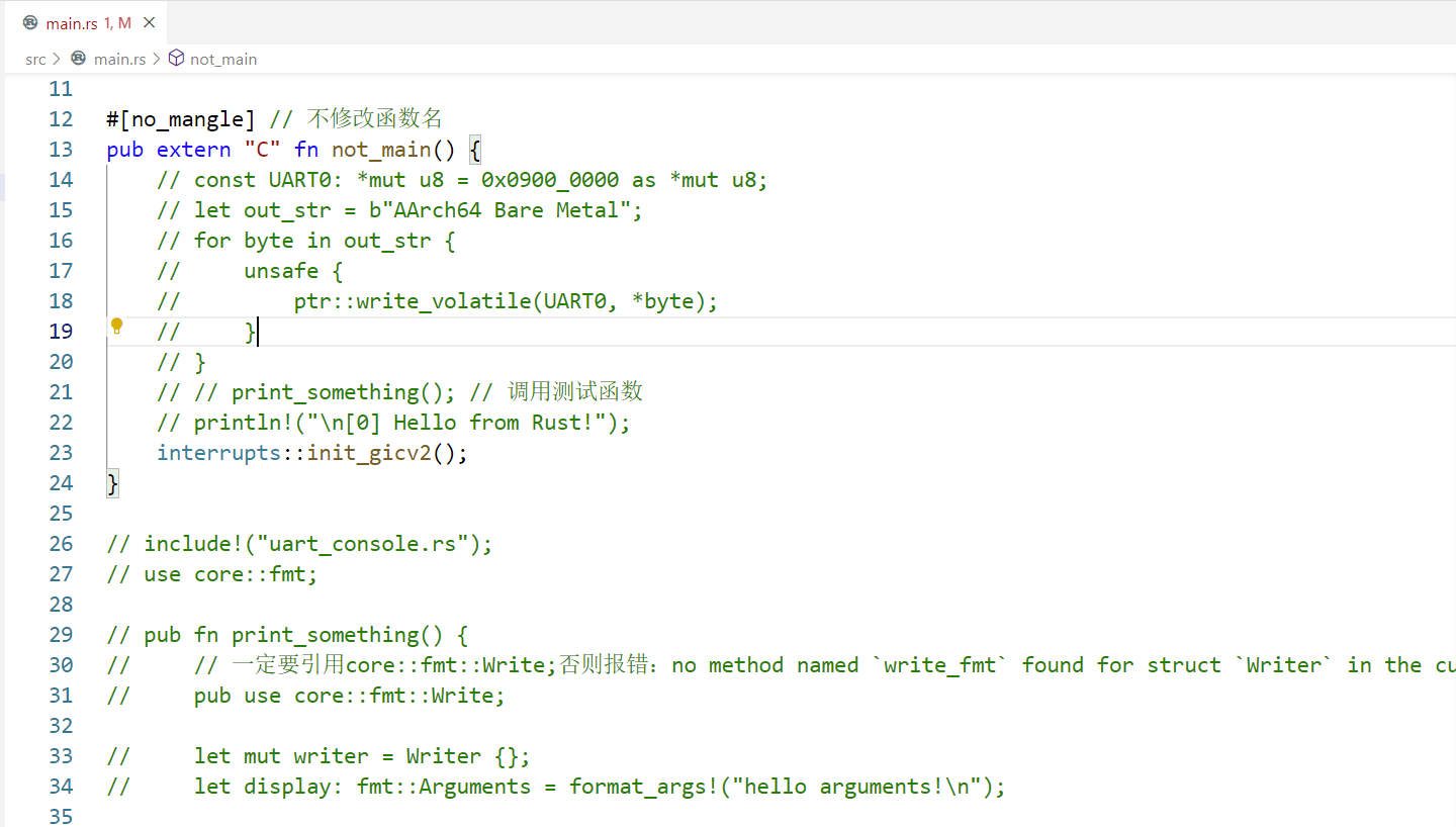
not_main()函数中移除不需要的代码
只保留一个println!宏以及中断初始化函数 init_gicv2()即可。print_something()函数我们亦不再用到,移除其相关代码 。
现在看起来就清爽 多了~src/interrupts.rs中有很多没有用到的常量和函数 ,通常称为dead_code,但是为了保证完整性 我们不选择删除它们 ,而是忽略 掉。src/main.rs中加入
1 #![allow(dead_code)] // 忽略dead_code
最后一个warning 在aarch64-unknown-none-softfloat.json中
1
2
3
4
5
6
7
8
"abi-blacklist": [ "stdcall", "fastcall", "vectorcall", "thiscall", "win64", "sysv64" ],
这个abi-blacklist推测是屏蔽一些接口 ,我们并没有调用这些接口 ,所以直接移除 。
至此我们的warnings 已经 全部处理(忽略) 完了。
2. 实现
参考代码:下载
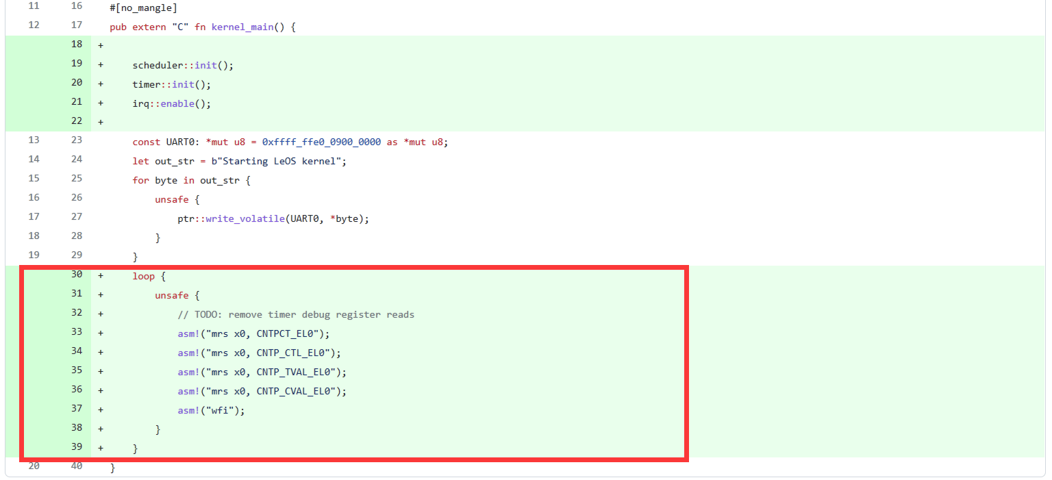
在查阅大量的资料 后,我找到了本次实验的原型(?) LeOS 以及其对应的时钟中断 部分的博客 。仔细阅读可以发现他实现时钟中断 的Commit 。noionion 的合作 及其帮助 下,我们发现了LeOS 关于时钟中断 的实现与实验四 中断 中有一些不一样 的地方:
在初始化中断 时,LeOS 还多了以下代码 :
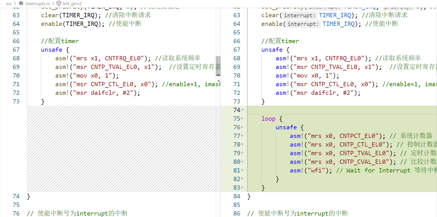
因此我们在src/interrupts.rs下的init_gicv2()函数尾部 添加以下代码:
1
2
3
4
5
6
7
8
9
loop { unsafe { asm!("mrs x0, CNTPCT_EL0"); // 系统计数器 asm!("mrs x0, CNTP_CTL_EL0"); // 控制计数器 asm!("mrs x0, CNTP_TVAL_EL0"); // 定时计数器 asm!("mrs x0, CNTP_CVAL_EL0"); // 比较计数器 asm!("wfi"); // Wait for Interrupt 等待中断,下一次中断发生前都停止在此处 } }
这里的五句 asm! 其实前四句 是无效操作 ,可以仅执行最后一句 。loop {} 亦可放在 not_main() 函数中,调用 init_gicv2() 初始化后。
编译 并运行
1 cargo build && qemu-system-aarch64 -machine virt -m 1024M -cpu cortex-a53 -nographic -kernel target/aarch64-unknown-none-softfloat/debug/rui_armv8_os
在运行 后,首先会输出
大约1s 后会输出
说明这次我们成功 调用了el1_irq()回调函数 !问题 是,时钟中断 的理想状态 应是每隔1s 就会调用一次el1_irq()回调函数 ,这里调用一次后却不再变化 了。catch()函数在调用第一个参数ctx时会发生阻塞 ,具体原因不详 。
若想修复 这个问题 ,可以编辑.cargo/config.toml,清空 然后改为以下内容
1
2
3
4
5
6
[unstable] build-std = ["core", "compiler_builtins"] [build] target = "aarch64-unknown-none-softfloat" rustflags = ["-C","link-arg=-Taarch64-qemu.ld", "-C", "target-cpu=cortex-a53", "-D", "warnings"]
因此我们修改该函数 ,编辑interrupts.rs:
1
2
3
4
5
6
// ······ // 调用我们的print!宏打印异常信息,你也可以选择打印异常发生时所有寄存器的信息 fn catch(ctx: &mut ExceptionCtx, name: &str) { crate::print!("{}\n", name); } // ······
然后编译运行
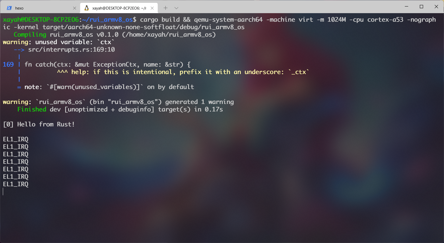
可以发现现在确实能够一直触发中断 并且输出回调函数名 了。但这每次输出间隔 的时间太短 了吧!概念 :
在ARM体系结构 中,处理器内部 有通用计时器 ,通用计时器 包含一组比较器 ,用来与系统计数器(CNTPCT_EL0)进行比较,一旦 通用计时器 的值小于等于系统计数器 时便会产生时钟中断 。
比较寄存器(CNTP_CVAL_EL0) 有64位,如果设置 了之后,当系统计数器达到或超过 了这个值 之后,就会触发定时器中断 。定时寄存器(CNTP_TVAL_EL0) 有32位,如果设置 了之后,会将比较寄存器 设置成当前系统计数器 加上设置的定时寄存器 的值。
详见此处
因此我们若想要有延时效果 ,需要在调用el1_irq()回调函数 时再次写入定时寄存器 。
1
2
asm!("mrs x1, CNTFRQ_EL0"); asm!("msr CNTP_TVAL_EL0, x1");
此时再编译运行 ,我们就已经成功 做到每1s 处理一次时钟中断 了!
五、输入
参考代码:下载
QEMU 的virt机器 默认没有键盘 作为输入设备 ,但当我们执行QEMU 使用-nographic参数(Disable graphical output and redirect serial I/Os to console)时QEMU 会将串口重定向 到控制台 ,因此我们可以使用UART 作为输入设备 。
1. 安装tock-registers库
在实验四 中,针对GICD ,GICC ,TIMER 等硬件 我们定义了大量 的常量 和寄存器值 ,这在使用时过于繁琐 也容易出错 。因此我们决定采用tock-registers 库。
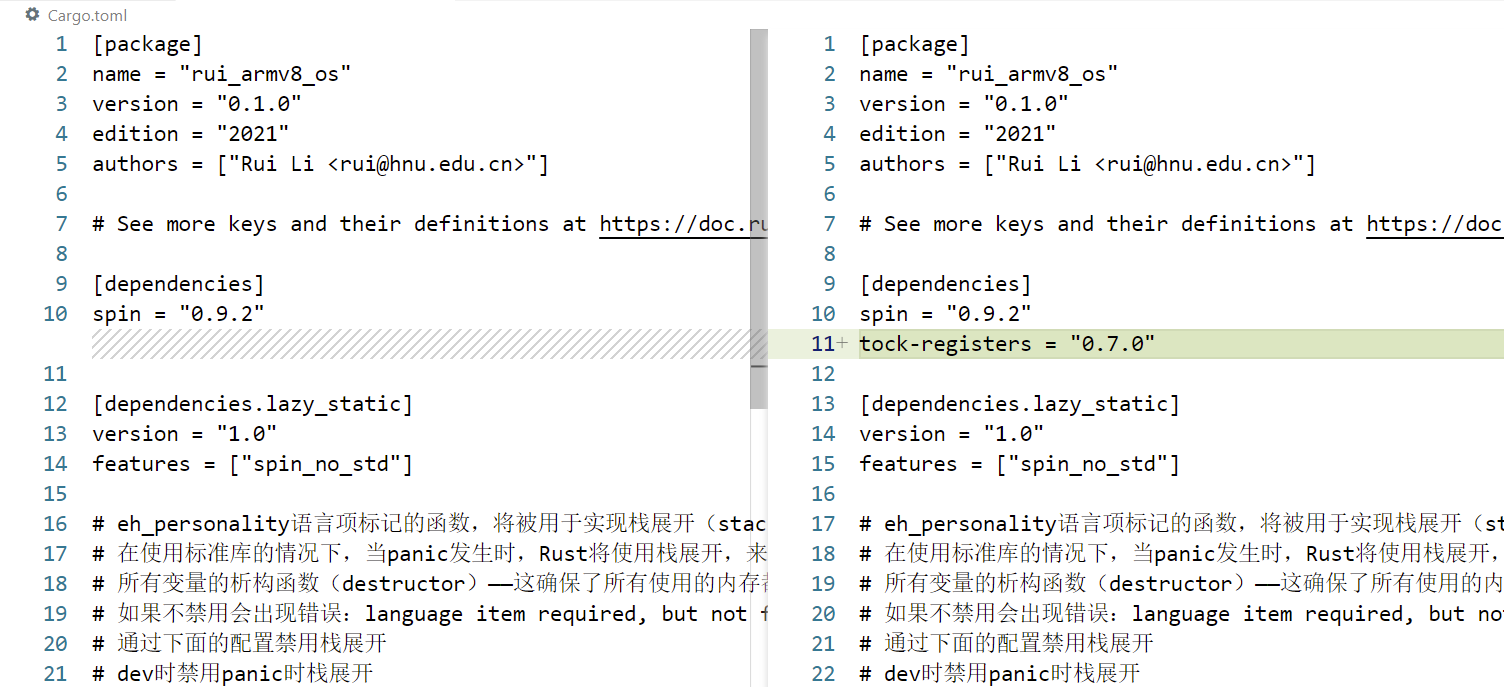
在Cargo.toml中的[dependencies]处中加入依赖 :
1 tock-registers = "0.7.0"
2. 重构
为了不至于使src/uart_console.rs文件过长,我们选择重构 uart_console.rs。
首先进入项目根目录 ,创建src/uart_console目录
将原uart_console.rs更名 为mod.rs,且置于src/uart_console目录下
1 mv src/uart_console.rs src/uart_console/mod.rs
最后新建 src/uart_console/pl011.rs
1 touch src/uart_console/pl011.rs
依据tock_registers 库的要求对pl011所涉及到的寄存器 进行描述。src/uart_console/pl011.rs
1
2
3
4
5
6
7
8
9
10
11
12
13
14
15
16
17
18
19
20
21
22
23
24
25
26
27
28
29
30
31
32
33
34
35
36
37
38
39
40
41
42
43
44
45
46
47
48
49
50
51
52
53
54
55
56
57
58
59
60
61
62
63
64
65
66
67
68
69
70
71
72
73
74
75
76
77
78
79
80
81
82
83
84
85
86
87
88
89
90
91
92
93
94
95
96
97
98
99
100
101
102
103
104
105
106
107
108
109
110
111
112
113
114
115
116
117
118
119
120
121
122
123
124
125
126
127
128
129
130
131
132
use tock_registers::{registers::{ReadOnly, ReadWrite, WriteOnly}, register_bitfields, register_structs}; pub const PL011REGS: *mut PL011Regs = (0x0900_0000) as *mut PL011Regs; register_bitfields![ u32, pub UARTDR [ DATA OFFSET(0) NUMBITS(8) [] ], /// Flag Register pub UARTFR [ /// Transmit FIFO full. The meaning of this bit depends on the /// state of the FEN bit in the UARTLCR_ LCRH Register. If the /// FIFO is disabled, this bit is set when the transmit /// holding register is full. If the FIFO is enabled, the TXFF /// bit is set when the transmit FIFO is full. TXFF OFFSET(6) NUMBITS(1) [], /// Receive FIFO empty. The meaning of this bit depends on the /// state of the FEN bit in the UARTLCR_H Register. If the /// FIFO is disabled, this bit is set when the receive holding /// register is empty. If the FIFO is enabled, the RXFE bit is /// set when the receive FIFO is empty. RXFE OFFSET(4) NUMBITS(1) [] ], /// Integer Baud rate divisor pub UARTIBRD [ /// Integer Baud rate divisor IBRD OFFSET(0) NUMBITS(16) [] ], /// Fractional Baud rate divisor pub UARTFBRD [ /// Fractional Baud rate divisor FBRD OFFSET(0) NUMBITS(6) [] ], /// Line Control register pub UARTLCR_H [ /// Parity enable. If this bit is set to 1, parity checking and generation /// is enabled, else parity is disabled and no parity bit added to the data frame. PEN OFFSET(1) NUMBITS(1) [ Disabled = 0, Enabled = 1 ], /// Two stop bits select. If this bit is set to 1, two stop bits are transmitted /// at the end of the frame. STP2 OFFSET(3) NUMBITS(1) [ Stop1 = 0, Stop2 = 1 ], /// Enable FIFOs. FEN OFFSET(4) NUMBITS(1) [ Disabled = 0, Enabled = 1 ], /// Word length. These bits indicate the number of data bits /// transmitted or received in a frame. WLEN OFFSET(5) NUMBITS(2) [ FiveBit = 0b00, SixBit = 0b01, SevenBit = 0b10, EightBit = 0b11 ] ], /// Control Register pub UARTCR [ /// Receive enable. If this bit is set to 1, the receive /// section of the UART is enabled. Data reception occurs for /// UART signals. When the UART is disabled in the middle of /// reception, it completes the current character before /// stopping. RXE OFFSET(9) NUMBITS(1) [ Disabled = 0, Enabled = 1 ], /// Transmit enable. If this bit is set to 1, the transmit /// section of the UART is enabled. Data transmission occurs /// for UART signals. When the UART is disabled in the middle /// of transmission, it completes the current character before /// stopping. TXE OFFSET(8) NUMBITS(1) [ Disabled = 0, Enabled = 1 ], /// UART enable UARTEN OFFSET(0) NUMBITS(1) [ /// If the UART is disabled in the middle of transmission /// or reception, it completes the current character /// before stopping. Disabled = 0, Enabled = 1 ] ], pub UARTIMSC [ RXIM OFFSET(4) NUMBITS(1) [ Disabled = 0, Enabled = 1 ] ], /// Interupt Clear Register pub UARTICR [ /// Meta field for all pending interrupts ALL OFFSET(0) NUMBITS(11) [ Clear = 0x7ff ] ] ]; register_structs! { pub PL011Regs { (0x00 => pub dr: ReadWrite<u32, UARTDR::Register>), // 0x00 (0x04 => __reserved_0), // 0x04 (0x18 => pub fr: ReadOnly<u32, UARTFR::Register>), // 0x18 (0x1c => __reserved_1), // 0x1c (0x24 => pub ibrd: WriteOnly<u32, UARTIBRD::Register>), // 0x24 (0x28 => pub fbrd: WriteOnly<u32, UARTFBRD::Register>), // 0x28 (0x2C => pub lcr_h: WriteOnly<u32, UARTLCR_H::Register>), // 0x2C (0x30 => pub cr: WriteOnly<u32, UARTCR::Register>), // 0x30 (0x34 => __reserved_2), // 0x34 (0x38 => pub imsc: ReadWrite<u32, UARTIMSC::Register>), // 0x38 (0x44 => pub icr: WriteOnly<u32, UARTICR::Register>), // 0x44 (0x48 => @END), } }
register_bitfields!宏 按照寄存器 的位结构 进行描述 ,注意最后要加分号”;”,只要 注册 自己想处理 的位 即可。
register_structs!宏 最后需加上 (0x** => @END) ,表示结束。
3. 数据接收中断 编辑src/uart_console/mod.rs,修改Writer 的初始化方式
1
2
3
4
5
6
7
8
9
10
11
12
13
14
15
16
17
18
19
20
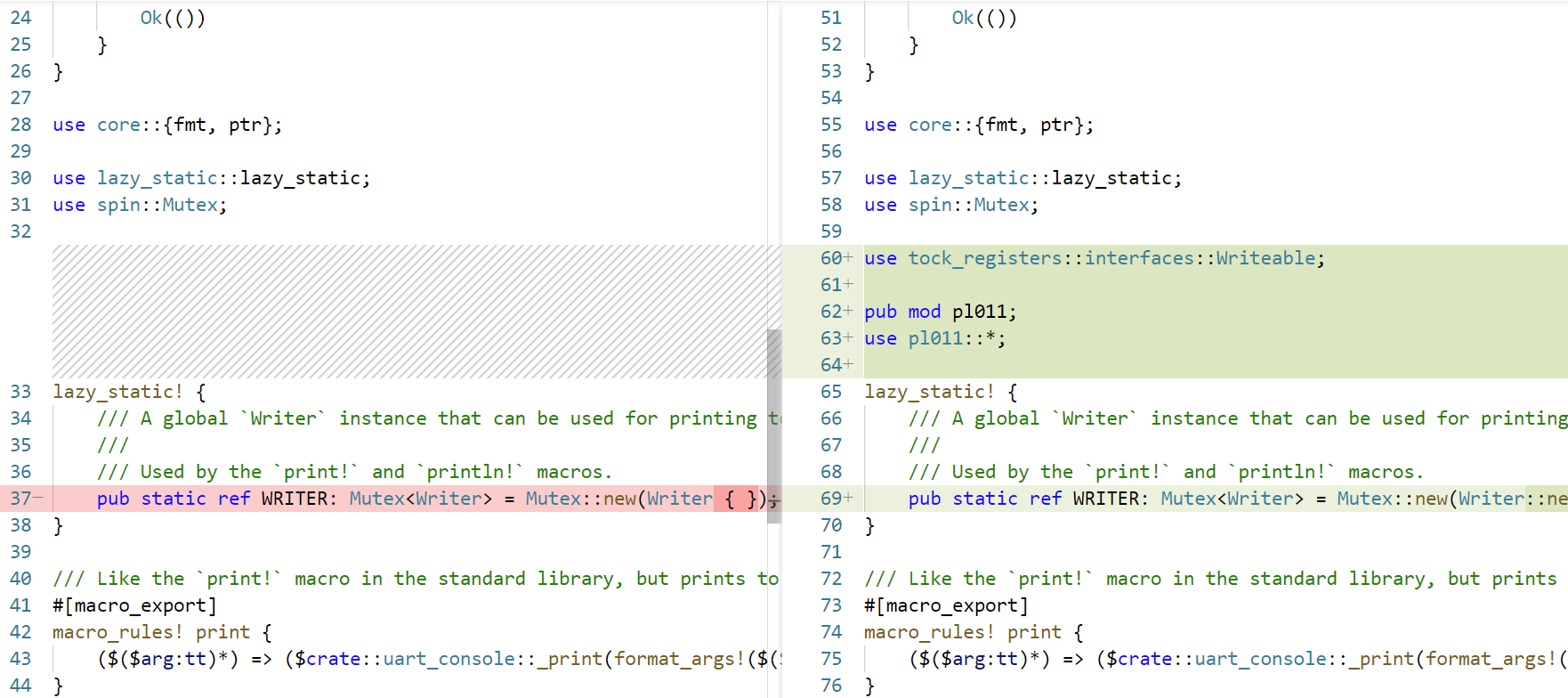
// ······ use core::{fmt, ptr}; use lazy_static::lazy_static; use spin::Mutex; use tock_registers::interfaces::Writeable; pub mod pl011; use pl011::*; lazy_static! { /// A global `Writer` instance that can be used for printing to the VGA text buffer. /// /// Used by the `print!` and `println!` macros. pub static ref WRITER: Mutex<Writer> = Mutex::new(Writer::new()); } /// Like the `print!` macro in the standard library, but prints to the VGA text buffer. // ······
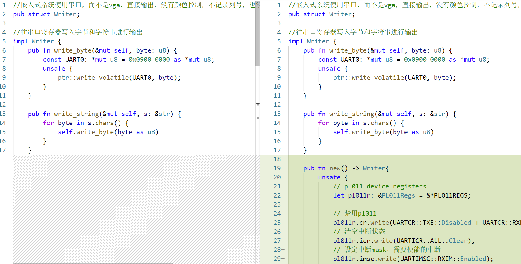
编辑src/uart_console/mod.rs,为Writer 结构实现构造函数
1
2
3
4
5
6
7
8
9
10
11
12
13
14
15
16
17
18
19
20
21
22
23
24
25
26
27
28
29
30
31
32
33
34
35
36
37
38
39
40
41
42
43
//嵌入式系统使用串口,而不是vga,直接输出,没有颜色控制,不记录列号,也没有frame buffer,所以采用空结构 pub struct Writer; //往串口寄存器写入字节和字符串进行输出 impl Writer { pub fn write_byte(&mut self, byte: u8) { // ······ } pub fn write_string(&mut self, s: &str) { // ······ } pub fn new() -> Writer{ unsafe { // pl011 device registers let pl011r: &PL011Regs = &*PL011REGS; // 禁用pl011 pl011r.cr.write(UARTCR::TXE::Disabled + UARTCR::RXE::Disabled + UARTCR::UARTEN::Disabled); // 清空中断状态 pl011r.icr.write(UARTICR::ALL::Clear); // 设定中断mask,需要使能的中断 pl011r.imsc.write(UARTIMSC::RXIM::Enabled); // IBRD = UART_CLK / (16 * BAUD_RATE) // FBRD = ROUND((64 * MOD(UART_CLK,(16 * BAUD_RATE))) / (16 * BAUD_RATE)) // UART_CLK = 24M // BAUD_RATE = 115200 pl011r.ibrd.write(UARTIBRD::IBRD.val(13)); pl011r.fbrd.write(UARTFBRD::FBRD.val(1)); // 8N1 FIFO enable pl011r.lcr_h.write(UARTLCR_H::WLEN::EightBit + UARTLCR_H::PEN::Disabled + UARTLCR_H::STP2::Stop1 + UARTLCR_H::FEN::Enabled); // enable pl011 pl011r.cr.write(UARTCR::UARTEN::Enabled + UARTCR::RXE::Enabled + UARTCR::TXE::Enabled); } Writer } } impl core::fmt::Write for Writer { // ······
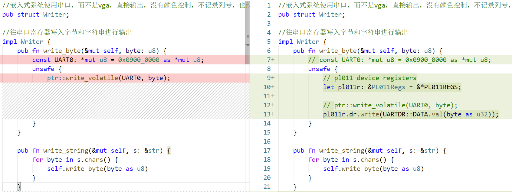
继续编辑src/uart_console/mod.rs,修改write_byte()函数,使用我们通过宏 描述的寄存器
1
2
3
4
5
6
7
8
9
10
11
12
13
14
15
16
17
18
//嵌入式系统使用串口,而不是vga,直接输出,没有颜色控制,不记录列号,也没有frame buffer,所以采用空结构 pub struct Writer; //往串口寄存器写入字节和字符串进行输出 impl Writer { pub fn write_byte(&mut self, byte: u8) { // const UART0: *mut u8 = 0x0900_0000 as *mut u8; unsafe { // pl011 device registers let pl011r: &PL011Regs = &*PL011REGS; // ptr::write_volatile(UART0, byte); pl011r.dr.write(UARTDR::DATA.val(byte as u32)); } } pub fn write_string(&mut self, s: &str) { // ······
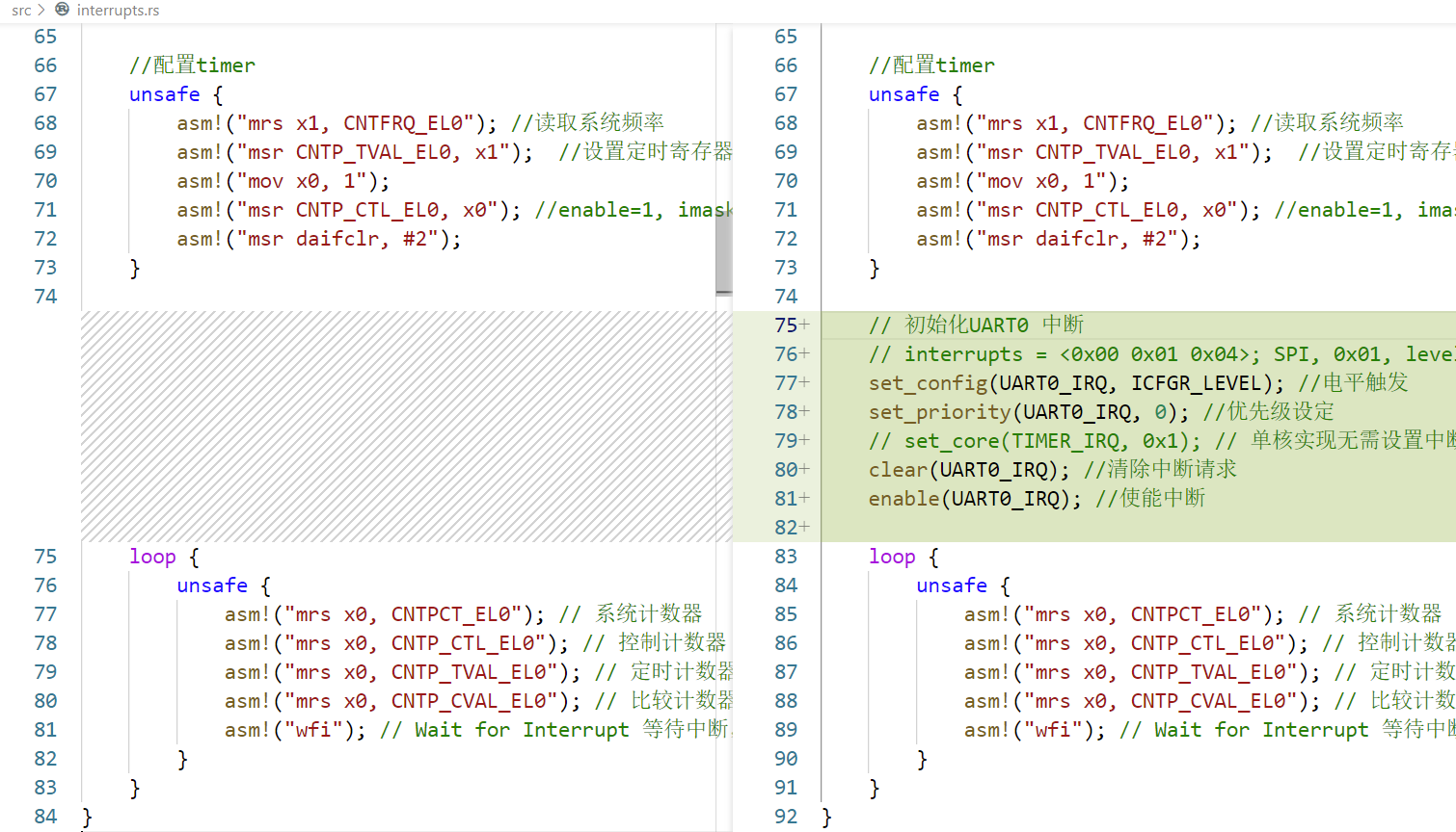
编辑src/interrupts.rs,修改init_gicv2()函数,对UART 的数据接收中断 进行初始化 :
1
2
3
4
5
6
7
8
9
10
11
12
13
14
15
16
17
18
// ······ //配置timer unsafe { // ······ } // 初始化UART0 中断 // interrupts = <0x00 0x01 0x04>; SPI, 0x01, level set_config(UART0_IRQ, ICFGR_LEVEL); //电平触发 set_priority(UART0_IRQ, 0); //优先级设定 // set_core(TIMER_IRQ, 0x1); // 单核实现无需设置中断目标核 clear(UART0_IRQ); //清除中断请求 enable(UART0_IRQ); //使能中断 loop { // ······ } // ······
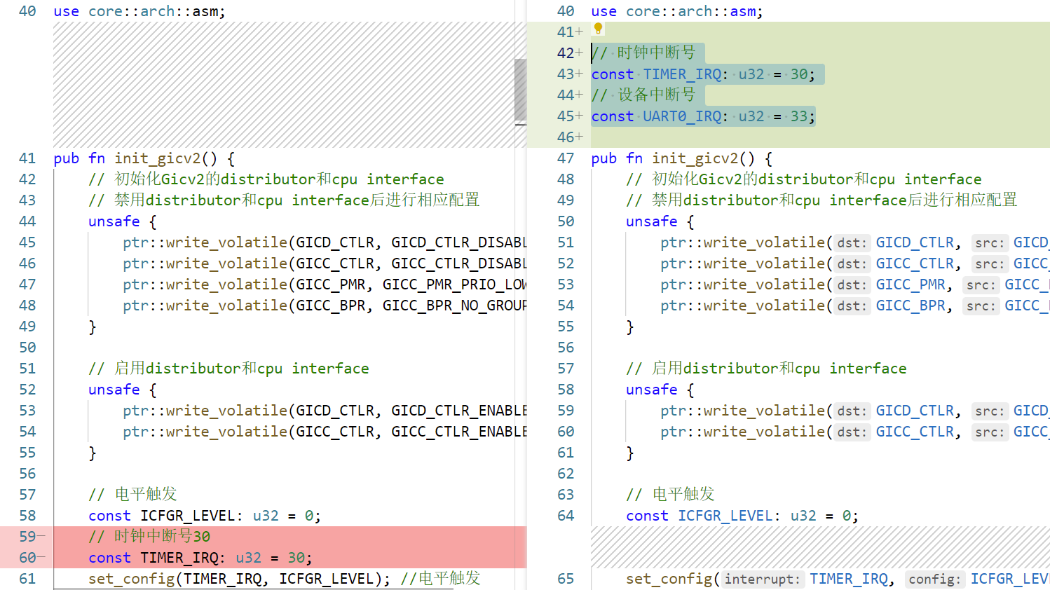
编辑src/interrupts.rs,接下来我们定义UART0_IRQ全局常量 ,同时把TIMER_IRQ也修改为全局常量
1
2
3
4
// 时钟中断号 const TIMER_IRQ: u32 = 30; // 设备中断号 const UART0_IRQ: u32 = 33;
继续编辑src/interrupts.rs,对UART 的数据接收中断 进行处理 ,并修改timer中断 的处理方法 ,使之每隔2秒输出一个点 。文末 添加以下三个函数 。
1
2
3
4
5
6
7
8
9
10
11
12
13
14
15
16
17
18
19
20
21
22
23
24
25
26
27
28
29
30
31
32
33
34
35
36
37
38
39
40
41
42
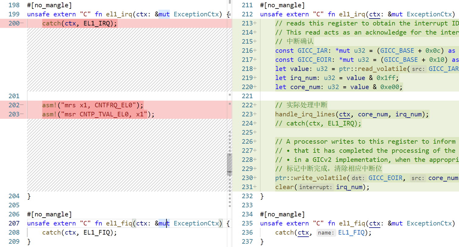
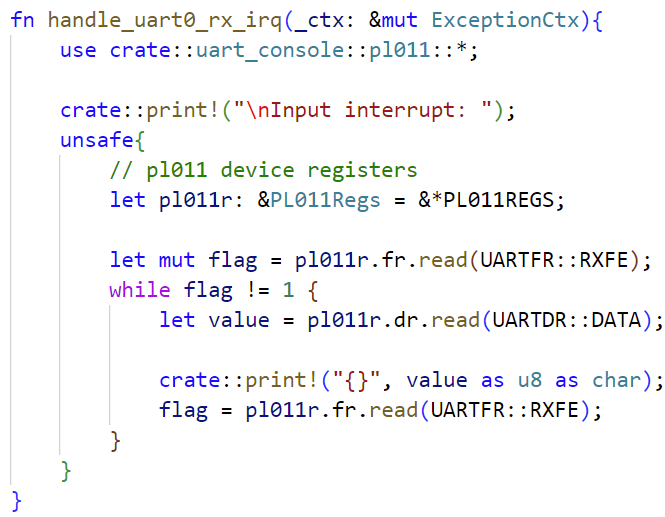
use tock_registers::interfaces::Readable; fn handle_irq_lines(ctx: &mut ExceptionCtx, _core_num: u32, irq_num: u32) { if irq_num == TIMER_IRQ { handle_timer_irq(ctx); }else if irq_num == UART0_IRQ { handle_uart0_rx_irq(ctx); } else{ catch(ctx, EL1_IRQ); } } fn handle_timer_irq(_ctx: &mut ExceptionCtx){ crate::print!("."); // 每2秒产生一次中断 unsafe { asm!("mrs x1, CNTFRQ_EL0"); asm!("add x1, x1, x1"); asm!("msr CNTP_TVAL_EL0, x1"); } } fn handle_uart0_rx_irq(_ctx: &mut ExceptionCtx){ use crate::uart_console::pl011::*; crate::print!("\nInput interrupt: "); unsafe{ // pl011 device registers let pl011r: &PL011Regs = &*PL011REGS; let mut flag = pl011r.fr.read(UARTFR::RXFE); while flag != 1 { let value = pl011r.dr.read(UARTDR::DATA); crate::print!("{}", value as u8 as char); flag = pl011r.fr.read(UARTFR::RXFE); } } }
继续编辑src/interrupts.rs,修改el1_irq()函数
1
2
3
4
5
6
7
8
9
10
11
12
13
14
15
16
17
18
19
20
21
22
#[no_mangle] unsafe extern "C" fn el1_irq(ctx: &mut ExceptionCtx) { // reads this register to obtain the interrupt ID of the signaled interrupt. // This read acts as an acknowledge for the interrupt. // 中断确认 const GICC_IAR: *mut u32 = (GICC_BASE + 0x0c) as *mut u32; const GICC_EOIR: *mut u32 = (GICC_BASE + 0x10) as *mut u32; let value: u32 = ptr::read_volatile(GICC_IAR); let irq_num: u32 = value & 0x1ff; let core_num: u32 = value & 0xe00; // 实际处理中断 handle_irq_lines(ctx, core_num, irq_num); // catch(ctx, EL1_IRQ); // A processor writes to this register to inform the CPU interface either: // • that it has completed the processing of the specified interrupt // • in a GICv2 implementation, when the appropriate GICC_CTLR.EOImode bit is set to 1, to indicate that the interface should perform priority drop for the specified interrupt. // 标记中断完成,清除相应中断位 ptr::write_volatile(GICC_EOIR, core_num | irq_num); clear(irq_num); }
之前我们修改了catch()函数,没有调用ctx参数,所以会有一个warning ,这里我们选择再次将其忽略 src/main.rs
1 #![allow(dead_code, unused_variables)] // 忽略dead_code
并且在src/uart_console/mod.rs中,有一个未使用的core::ptr引用,将其移除
接下来编译 并运行
1 cargo build && qemu-system-aarch64 -machine virt -m 1024M -cpu cortex-a53 -nographic -kernel target/aarch64-unknown-none-softfloat/debug/rui_armv8_os
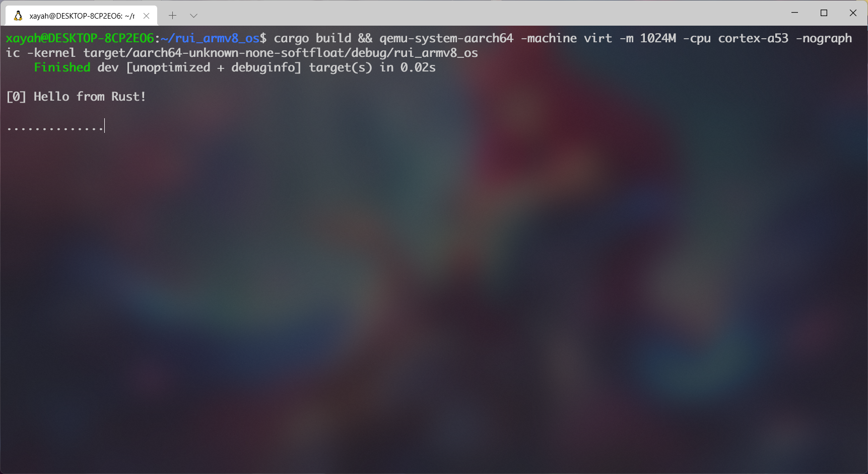
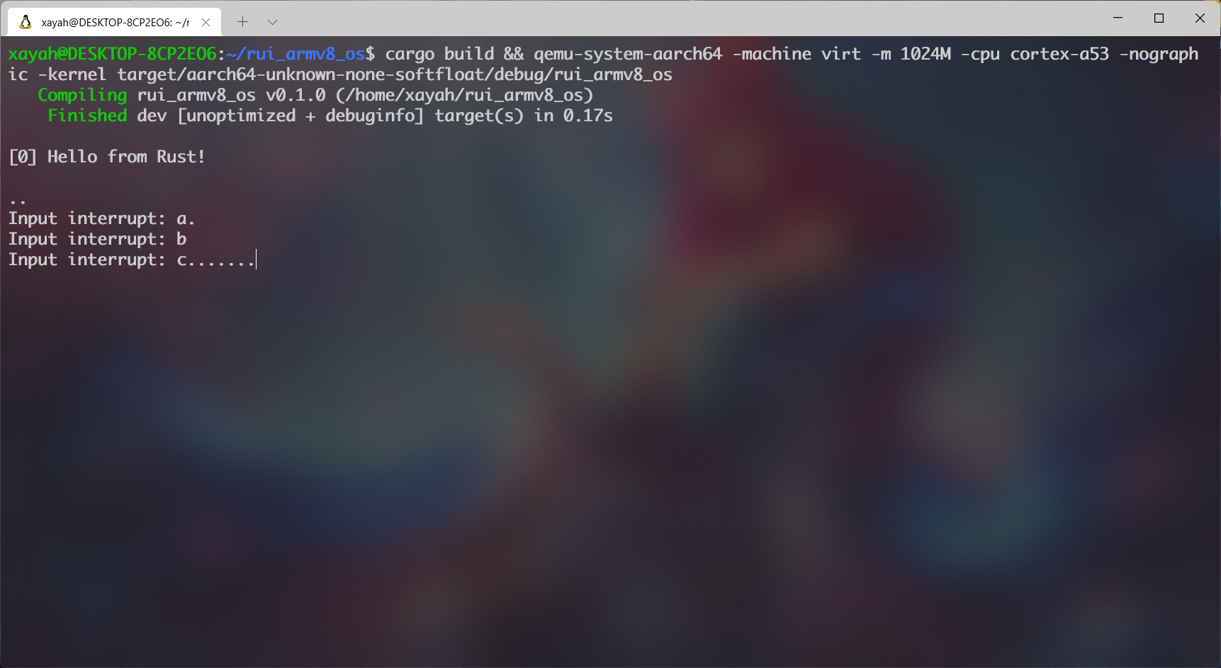
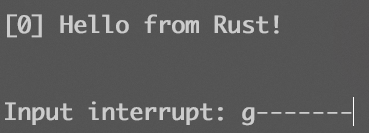
可以看到每过2s 就会打一个点 。顺序 输入a 、b 、c ,则会触发输入中断
六、GPIO关机
参考代码:下载
1. 原理 查看virt.dts,可以发现 :
1
2
3
4
5
6
7
8
9
10
11
12
13
14
15
16
17
18
19
20
21
22
gpio-keys { #address-cells = <0x01>; #size-cells = <0x00>; compatible = "gpio-keys"; poweroff { gpios = <0x8003 0x03 0x00>; linux,code = <0x74>; label = "GPIO Key Poweroff"; }; }; pl061@9030000 { phandle = <0x8003>; clock-names = "apb_pclk"; clocks = <0x8000>; interrupts = <0x00 0x07 0x04>; gpio-controller; #gpio-cells = <0x02>; compatible = "arm,pl061\0arm,primecell"; reg = <0x00 0x9030000 0x00 0x1000>; };
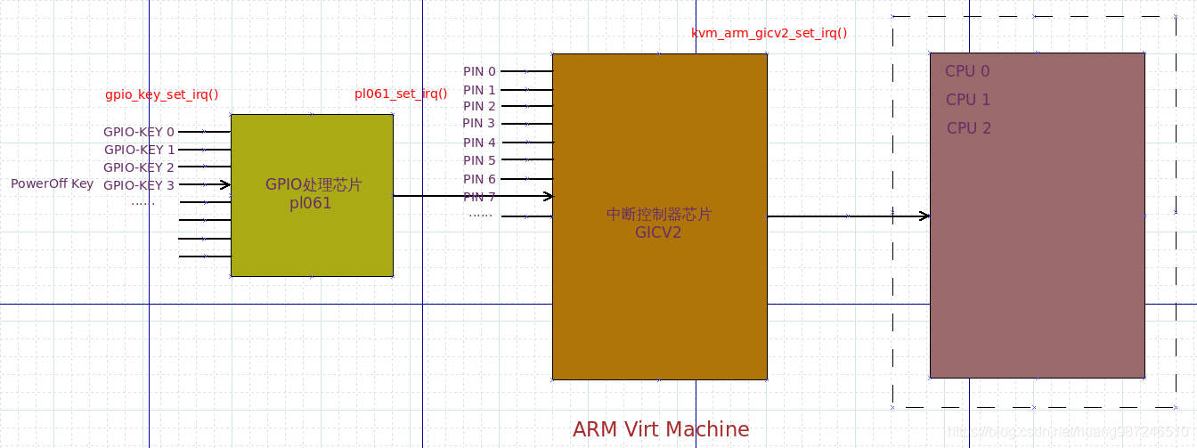
其中gpio-keys 中定义了一个poweroff 键, gpios = <0x8003 0x03 0x00> 中的第一项0x8003 表示它的phandle 是0x8003 , 即pl061@9030000 ,也即gpio-keys 是设备pl061 的组成部分,第二项0x03 表示该键是pl061 的第三根GPIO线 ,第三项是flag ,且pl061 的寄存器映射到了内存0x9030000 开始的位置。如下图所示。
2. 实现 新建src/pl061.rs
编辑src/pl061.rs,通过tock-registers 描述寄存器
1
2
3
4
5
6
7
8
9
10
11
12
13
14
15
16
17
18
19
20
21
22
23
use tock_registers::{registers::{ReadWrite, WriteOnly}, register_bitfields, register_structs}; pub const PL061REGS: *mut PL061Regs = (0x0903_0000) as *mut PL061Regs; register_bitfields![ u32, pub GPIOIE [ IO3 OFFSET(3) NUMBITS(1) [ Disabled = 0, Enabled = 1 ] ], ]; register_structs! { pub PL061Regs { (0x000 => __reserved_0), // 0x000 (0x410 => pub ie: ReadWrite<u32, GPIOIE::Register>), // 0x410 (0x414 => __reserved_1), // 0x414 (0x41C => pub ic: WriteOnly<u32>), // 0x41C (0x420 => @END), // 0x420 } }
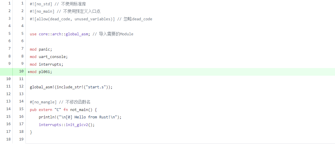
编辑src/main.rs,引入pl061 模块。
1
2
3
4
5
6
7
8
9
10
// ······ use core::arch::global_asm; // 导入需要的Module mod panic; mod uart_console; mod interrupts; mod pl061; global_asm!(include_str!("start.s")); // ······
编辑src/interrupts.rs,在init_gicv2函数中初始化pl061的GPIO中断
1
2
3
4
5
6
7
8
9
10
11
12
13
14
15
16
17
18
19
20
21
22
23
24
25
26
27
28
29
30
31
32
33
34
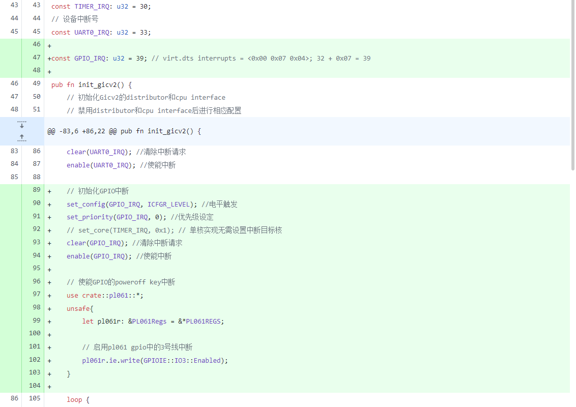
// ······ // 时钟中断号 const TIMER_IRQ: u32 = 30; // 设备中断号 const UART0_IRQ: u32 = 33; const GPIO_IRQ: u32 = 39; // virt.dts interrupts = <0x00 0x07 0x04>; 32 + 0x07 = 39 pub fn init_gicv2() { // 初始化Gicv2的distributor和cpu interface // 禁用distributor和cpu interface后进行相应配置 // ······ // 初始化GPIO中断 set_config(GPIO_IRQ, ICFGR_LEVEL); //电平触发 set_priority(GPIO_IRQ, 0); //优先级设定 // set_core(TIMER_IRQ, 0x1); // 单核实现无需设置中断目标核 clear(GPIO_IRQ); //清除中断请求 enable(GPIO_IRQ); //使能中断 // 使能GPIO的poweroff key中断 use crate::pl061::*; unsafe{ let pl061r: &PL061Regs = &*PL061REGS; // 启用pl061 gpio中的3号线中断 pl061r.ie.write(GPIOIE::IO3::Enabled); } loop { // ······ } } // ······
编辑src/interrupts.rs,引入tock_registers::interfaces::Writeable
1
2
3
4
5
6
7
// ······ use tock_registers::interfaces::Readable; use tock_registers::interfaces::Writeable; fn handle_irq_lines(ctx: &mut ExceptionCtx, _core_num: u32, irq_num: u32) { // ······ } // ······
编辑src/interrupts.rs,处理pl0613号GPIO线 引发的中断
1
2
3
4
5
6
7
8
9
10
11
12
13
14
15
16
17
18
19
20
21
22
23
24
25
26
27
28
29
30
31
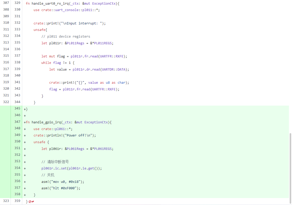
// ······ fn handle_irq_lines(ctx: &mut ExceptionCtx, _core_num: u32, irq_num: u32) { if irq_num == TIMER_IRQ { handle_timer_irq(ctx); }else if irq_num == UART0_IRQ { handle_uart0_rx_irq(ctx); }else if irq_num == GPIO_IRQ { handle_gpio_irq(ctx); } else{ catch(ctx, EL1_IRQ); } } fn handle_timer_irq(_ctx: &mut ExceptionCtx){ // ······ } // ······ fn handle_gpio_irq(_ctx: &mut ExceptionCtx){ use crate::pl061::*; crate::println!("Power off!\n"); unsafe { let pl061r: &PL061Regs = &*PL061REGS; // 清除中断信号 pl061r.ic.set(pl061r.ie.get()); // 关机 asm!("mov w0, #0x18"); asm!("hlt #0xF000"); } }
在 handle_gpio_irq() 函数里通过内联汇编 执行了指令hlt #0xF000 ,这里用到了ARM 的Semihosting 功能。
Semihosting 的作用:能够让bare-metal 的ARM 设备通过拦截指定的SVC指令 ,在连操作系统 都没有的环境中实现POSIX 中的许多标准函数 ,比如printf 、scanf 、open 、read 、write 等等。这些IO 操作将被Semihosting 协议转发到Host主机 上,然后由主机代为执行 。
编辑src/interrupts.rs,停止打点,方便后续测试观察
1
2
3
4
5
6
7
8
9
10
11
12
13
14
// ······ fn handle_timer_irq(_ctx: &mut ExceptionCtx){ // crate::print!("."); // 每2秒产生一次中断 unsafe { asm!("mrs x1, CNTFRQ_EL0"); asm!("add x1, x1, x1"); asm!("msr CNTP_TVAL_EL0, x1"); } } // ······
3. 执行
为了启用Semihosting 功能,在QEMU 执行时需要加入 -semihosting 参数
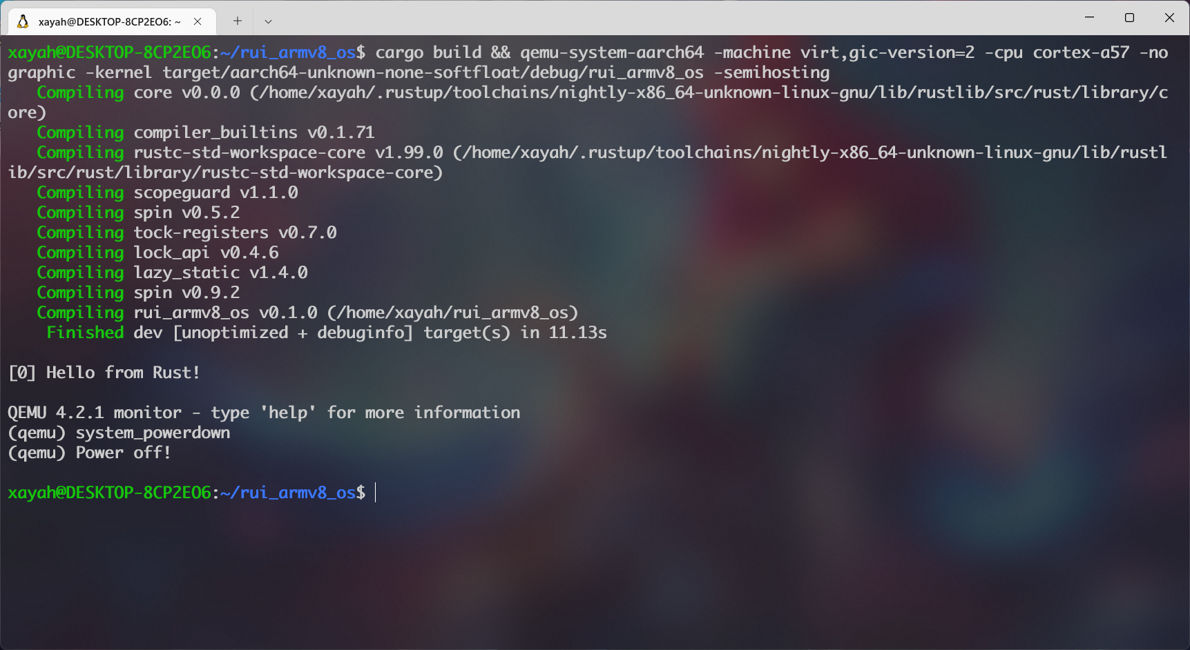
1 cargo build && qemu-system-aarch64 -machine virt,gic-version=2 -cpu cortex-a57 -nographic -kernel target/aarch64-unknown-none-softfloat/debug/rui_armv8_os -semihosting
先按Ctrl + A,松手再按C,然后输入system_powerdown执行关机。
七、死锁与简单处理
参考代码:下载
当多个任务 访问同一个资源(数据) 时就会引发竞争条件问题 ,这不仅在进程间 会出现,在操作系统 和进程间 也会出现。由竞争条件 引发的问题很难复现 和调试 ,这也是其最困难 的地方。本实验 的目的在于了解竞争条件 和死锁现象 ,并掌握 处理这些问题的初步方法 等。
勘误
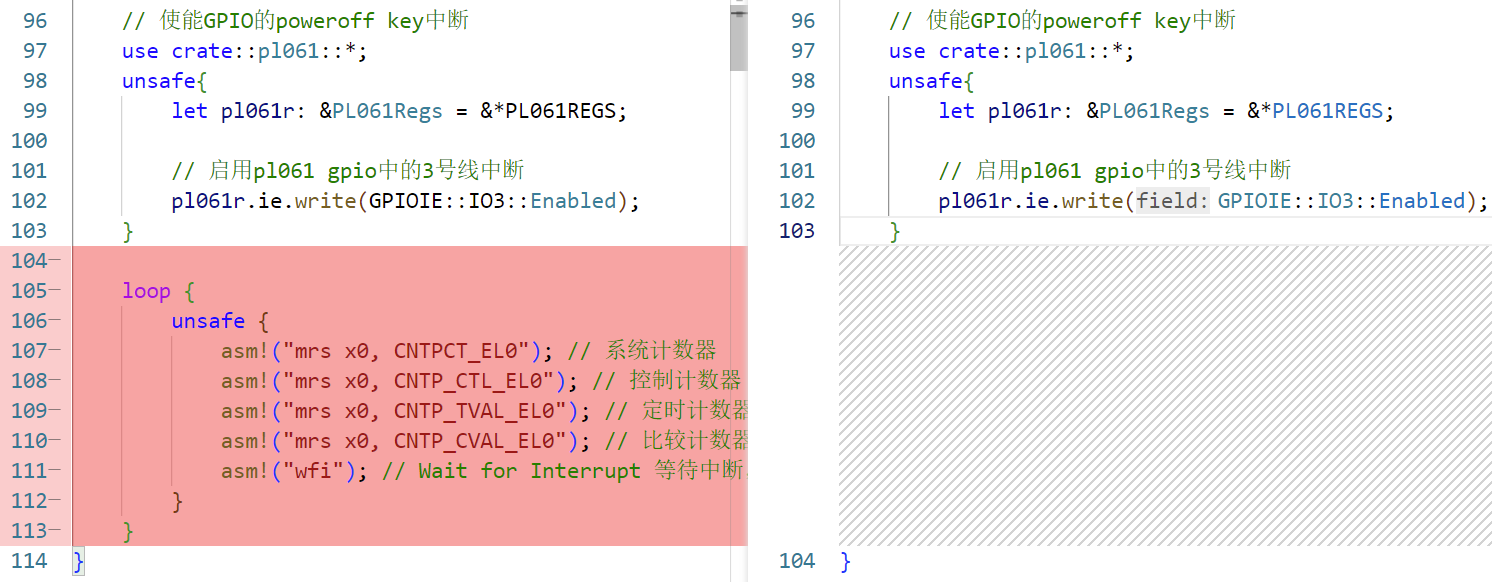
在src/interrupts.rs 的init_gicv2()函数中,我们之前使用了一个 循环 并使用内联汇编asm!(“wfi”)来 等待中断 ,实际上在之前的实验中,这里所有的内联汇编 都是没有必要的。当去掉这个循环 ,我们的OS 会串行执行完成 然后自动关机 ,从而导致后续的测试无效 。因此我们需要且仅需要 一个空循环 来使OS持续运行 ,以便后续的中断测试 。
编辑src/interrupts.rs,在init_gicv2()函数中移除loop{}循环。
编辑src/main.rs,在not_main()函数尾部添加loop{}空循环。
1
2
3
4
5
6
7
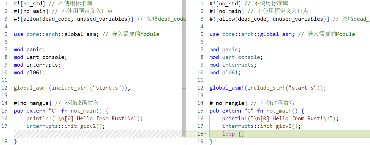
// ······ #[no_mangle] // 不修改函数名 pub extern "C" fn not_main() { println!("\n[0] Hello from Rust!\n"); interrupts::init_gicv2(); loop {} }
死锁的复现 首先编辑src/main.rs,在not_main()函数的空循环中调用print!宏
1
2
3
4
5
6
7
8
9
10
11
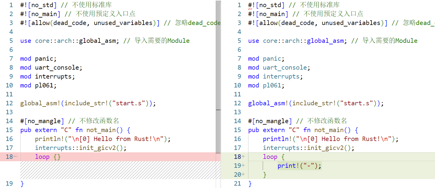
// ······ global_asm!(include_str!("start.s")); #[no_mangle] // 不修改函数名 pub extern "C" fn not_main() { println!("\n[0] Hello from Rust!\n"); interrupts::init_gicv2(); loop { print!("-"); } }
这里有两种方式复现死锁现象。
1. loop{}中print!宏与handle_uart0_rx_irq()中print!宏竞争 检查src/interrupts.rs中的handle_uart0_rx_irq()函数,可以看到我们之前写了一个输入中断回调函数,在函数中调用了print!宏输出信息。
直接编译并运行,预期在输入时触发死锁。
1 cargo build && qemu-system-aarch64 -machine virt,gic-version=2 -cpu cortex-a57 -nographic -kernel target/aarch64-unknown-none-softfloat/debug/rui_armv8_os -semihosting
不停地乱序敲击键盘,此时有概率出现卡死,按键无法再次输入内容,即触发死锁现象。
2. loop{}中print!宏与handle_timer_irq()中print!宏竞争 检查src/interrupts.rs中的handle_timer_irq()函数,可以看到我们之前写了一个时间中断回调函数,在函数中调用了print!宏打点。
但它之前被我们注释掉了,因此我们取消注释
然后我们编译并运行,预期在打第一个点时会触发死锁。
1 cargo build && qemu-system-aarch64 -machine virt,gic-version=2 -cpu cortex-a57 -nographic -kernel target/aarch64-unknown-none-softfloat/debug/rui_armv8_os -semihosting
实验按预期触发了死锁。
有时会在打第二个点时触发死锁。
死锁的简单处理 编辑src/uart_console/mod.rs,引入asm!宏
1
2
3
4
5
6
7
8
9
10
11
12
13
14
15
16
17
// ······ impl core::fmt::Write for Writer { fn write_str(&mut self, s: &str) -> fmt::Result { // ······ } } use core::{fmt, arch::asm}; use lazy_static::lazy_static; use spin::Mutex; use tock_registers::interfaces::Writeable; pub mod pl011; use pl011::*; // ······
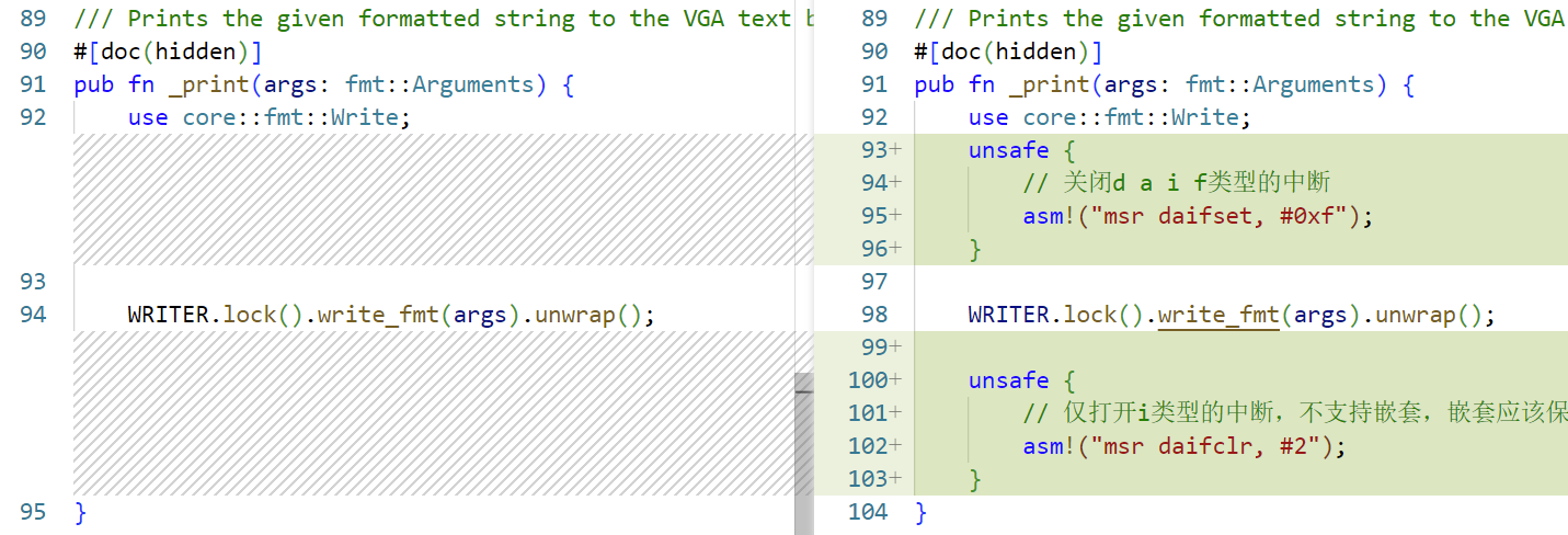
编辑src/uart_console/mod.rs中的_print()函数,在处理输入时先关闭中断,再打开。
1
2
3
4
5
6
7
8
9
10
11
12
13
14
15
16
17
// ······ /// Prints the given formatted string to the VGA text buffer through the global `WRITER` instance. #[doc(hidden)] pub fn _print(args: fmt::Arguments) { use core::fmt::Write; unsafe { // 关闭d a i f类型的中断 asm!("msr daifset, #0xf"); } WRITER.lock().write_fmt(args).unwrap(); unsafe { // 仅打开i类型的中断,不支持嵌套,嵌套应该保存状态,然后再恢复之前的状态 asm!("msr daifclr, #2"); } }
验证 此时再用上述两种方式测试死锁,发现死锁现象消失了~
八、内存管理
分页内存管理 是内存管理 的基本方法之一 。本实验的目的在于全面理解分页式内存管理 的基本方法 以及访问页表 ,完成地址转换 等的方法。
ARM v8的地址转换
ARM Cortex-A Series Programmer’s Guide for ARMv8-A
For EL0 and EL1 , there are two translation tables . TTBR0_EL1 provides translations for the bottom of Virtual Address space , which is typically application space and TTBR1_EL1 covers the top of Virtual Address space , typically kernel space . This split means that the OS mappings do not have to be replicated in the translation tables of each task.
即TTBR0 指向虚拟空间下半部分 通常用于应用程序 的空间,TTBR1 指向虚拟空间上半部分 通常用于内核 的空间。其中TTBR0 除了在EL1 中存在外,也在EL2 和EL3 中存在,但TTBR1 只在EL1 中存在。
TTBR0_ELn 和TTBR1_ELn 是页表基地址寄存器 ,地址转换 的过程如下所示
一、使用Identity Mapping映射
参考代码:下载
虚拟地址转换 很容易出错 也很难调试 ,所以我们从最简单的方式 开始,即采用Identity Mapping ,将虚拟地址 映射到相同 的物理地址 。
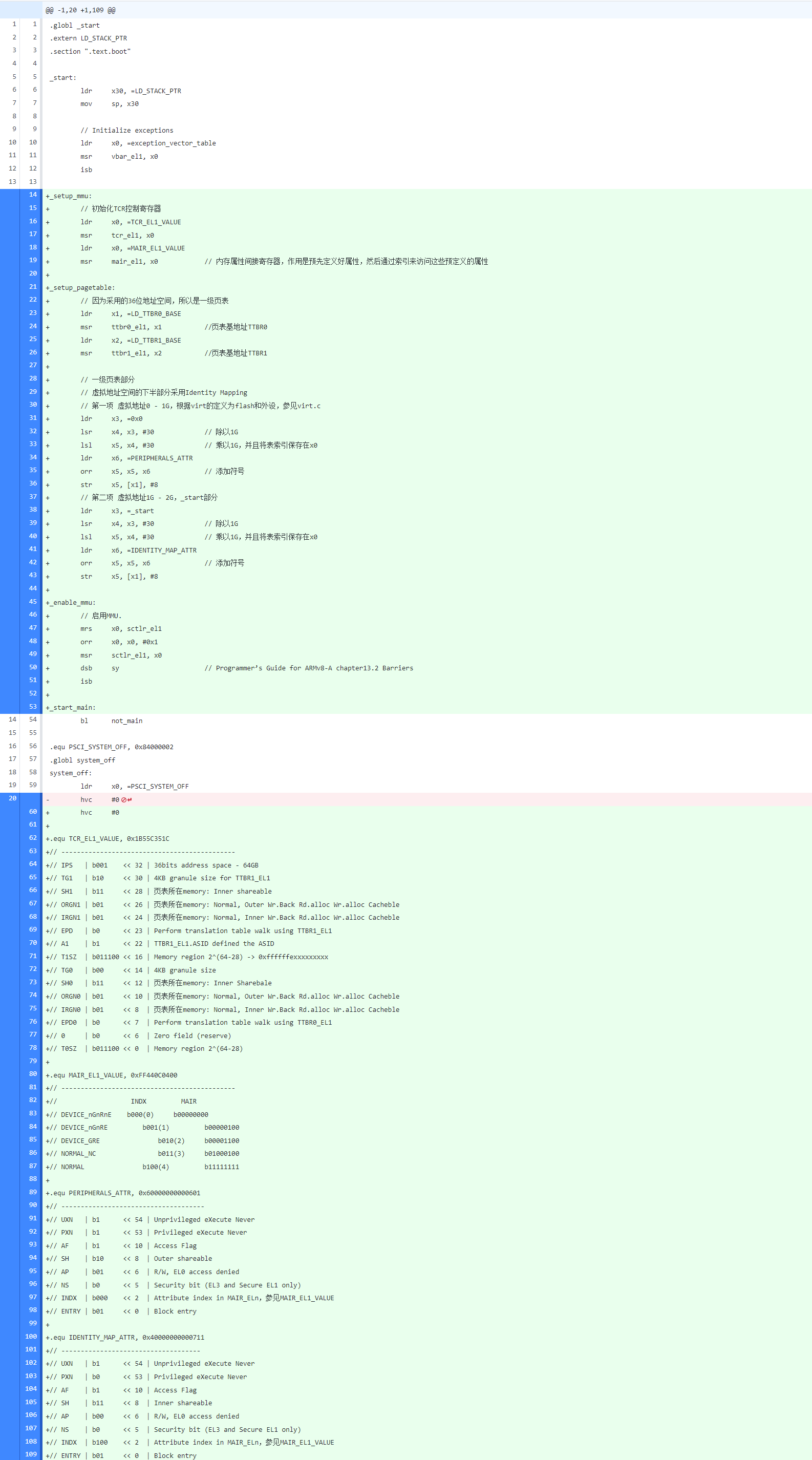
编辑src/start.s,初始化MMU 、页表 以及启用页表 。
1
2
3
4
5
6
7
8
9
10
11
12
13
14
15
16
17
18
19
20
21
22
23
24
25
26
27
28
29
30
31
32
33
34
35
36
37
38
39
40
41
42
43
44
45
46
47
48
49
50
51
52
53
54
55
56
57
58
59
60
61
62
63
64
65
66
67
68
69
70
71
72
73
74
75
76
77
78
79
80
81
82
83
84
85
86
87
88
89
90
91
92
93
94
95
96
97
98
99
100
101
102
103
104
105
106
107
108
109
.globl _start .extern LD_STACK_PTR .section ".text.boot" _start: ldr x30, =LD_STACK_PTR mov sp, x30 // Initialize exceptions ldr x0, =exception_vector_table msr vbar_el1, x0 isb _setup_mmu: // 初始化TCR控制寄存器 ldr x0, =TCR_EL1_VALUE msr tcr_el1, x0 ldr x0, =MAIR_EL1_VALUE msr mair_el1, x0 // 内存属性间接寄存器,作用是预先定义好属性,然后通过索引来访问这些预定义的属性 _setup_pagetable: // 因为采用的36位地址空间,所以是一级页表 ldr x1, =LD_TTBR0_BASE msr ttbr0_el1, x1 //页表基地址TTBR0 ldr x2, =LD_TTBR1_BASE msr ttbr1_el1, x2 //页表基地址TTBR1 // 一级页表部分 // 虚拟地址空间的下半部分采用Identity Mapping // 第一项 虚拟地址0 - 1G,根据virt的定义为flash和外设,参见virt.c ldr x3, =0x0 lsr x4, x3, #30 // 除以1G lsl x5, x4, #30 // 乘以1G,并且将表索引保存在x0 ldr x6, =PERIPHERALS_ATTR orr x5, x5, x6 // 添加符号 str x5, [x1], #8 // 第二项 虚拟地址1G - 2G,_start部分 ldr x3, =_start lsr x4, x3, #30 // 除以1G lsl x5, x4, #30 // 乘以1G,并且将表索引保存在x0 ldr x6, =IDENTITY_MAP_ATTR orr x5, x5, x6 // 添加符号 str x5, [x1], #8 _enable_mmu: // 启用MMU. mrs x0, sctlr_el1 orr x0, x0, #0x1 msr sctlr_el1, x0 dsb sy // Programmer’s Guide for ARMv8-A chapter13.2 Barriers isb _start_main: bl not_main .equ PSCI_SYSTEM_OFF, 0x84000002 .globl system_off system_off: ldr x0, =PSCI_SYSTEM_OFF hvc #0 .equ TCR_EL1_VALUE, 0x1B55C351C // --------------------------------------------- // IPS | b001 << 32 | 36bits address space - 64GB // TG1 | b10 << 30 | 4KB granule size for TTBR1_EL1 // SH1 | b11 << 28 | 页表所在memory: Inner shareable // ORGN1 | b01 << 26 | 页表所在memory: Normal, Outer Wr.Back Rd.alloc Wr.alloc Cacheble // IRGN1 | b01 << 24 | 页表所在memory: Normal, Inner Wr.Back Rd.alloc Wr.alloc Cacheble // EPD | b0 << 23 | Perform translation table walk using TTBR1_EL1 // A1 | b1 << 22 | TTBR1_EL1.ASID defined the ASID // T1SZ | b011100 << 16 | Memory region 2^(64-28) -> 0xffffffexxxxxxxxx // TG0 | b00 << 14 | 4KB granule size // SH0 | b11 << 12 | 页表所在memory: Inner Sharebale // ORGN0 | b01 << 10 | 页表所在memory: Normal, Outer Wr.Back Rd.alloc Wr.alloc Cacheble // IRGN0 | b01 << 8 | 页表所在memory: Normal, Inner Wr.Back Rd.alloc Wr.alloc Cacheble // EPD0 | b0 << 7 | Perform translation table walk using TTBR0_EL1 // 0 | b0 << 6 | Zero field (reserve) // T0SZ | b011100 << 0 | Memory region 2^(64-28) .equ MAIR_EL1_VALUE, 0xFF440C0400 // --------------------------------------------- // INDX MAIR // DEVICE_nGnRnE b000(0) b00000000 // DEVICE_nGnRE b001(1) b00000100 // DEVICE_GRE b010(2) b00001100 // NORMAL_NC b011(3) b01000100 // NORMAL b100(4) b11111111 .equ PERIPHERALS_ATTR, 0x60000000000601 // ------------------------------------- // UXN | b1 << 54 | Unprivileged eXecute Never // PXN | b1 << 53 | Privileged eXecute Never // AF | b1 << 10 | Access Flag // SH | b10 << 8 | Outer shareable // AP | b01 << 6 | R/W, EL0 access denied // NS | b0 << 5 | Security bit (EL3 and Secure EL1 only) // INDX | b000 << 2 | Attribute index in MAIR_ELn,参见MAIR_EL1_VALUE // ENTRY | b01 << 0 | Block entry .equ IDENTITY_MAP_ATTR, 0x40000000000711 // ------------------------------------ // UXN | b1 << 54 | Unprivileged eXecute Never // PXN | b0 << 53 | Privileged eXecute Never // AF | b1 << 10 | Access Flag // SH | b11 << 8 | Inner shareable // AP | b00 << 6 | R/W, EL0 access denied // NS | b0 << 5 | Security bit (EL3 and Secure EL1 only) // INDX | b100 << 2 | Attribute index in MAIR_ELn,参见MAIR_EL1_VALUE // ENTRY | b01 << 0 | Block entry
(如果预览不清晰 ,可以在新标签页 中打开图片 ,或者下载图片 ,然后放大 )
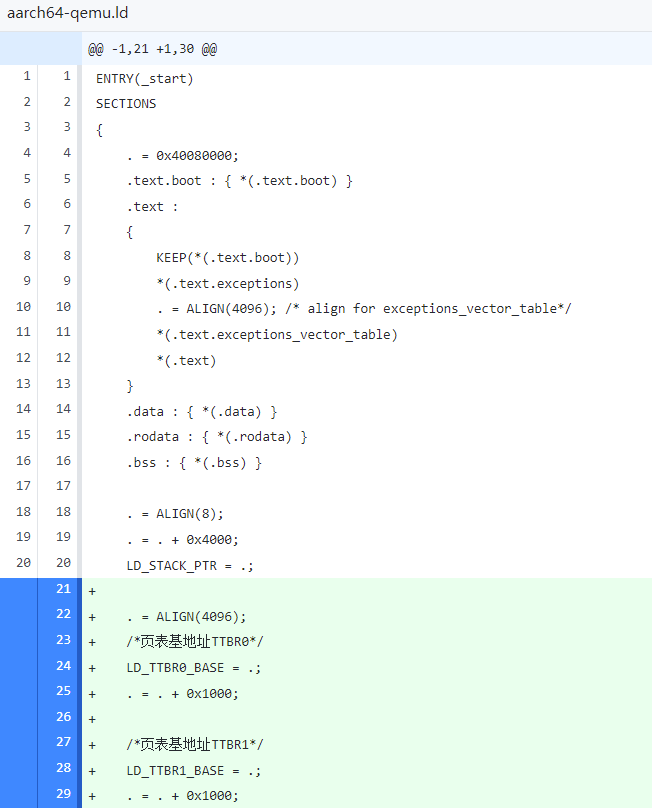
编辑aarch64-qemu.ld,定义前文中用到的LD_TTBR0_BASE和LD_TTBR1_BASE符号
1
2
3
4
5
6
7
8
9
10
11
12
13
14
15
16
17
18
19
20
21
22
23
24
25
26
27
28
29
30
ENTRY(_start) SECTIONS { . = 0x40080000; .text.boot : { *(.text.boot) } .text : { KEEP(*(.text.boot)) *(.text.exceptions) . = ALIGN(4096); /* align for exceptions_vector_table*/ *(.text.exceptions_vector_table) *(.text) } .data : { *(.data) } .rodata : { *(.rodata) } .bss : { *(.bss) } . = ALIGN(8); . = . + 0x4000; LD_STACK_PTR = .; . = ALIGN(4096); /*页表基地址TTBR0*/ LD_TTBR0_BASE = .; . = . + 0x1000; /*页表基地址TTBR1*/ LD_TTBR1_BASE = .; . = . + 0x1000; }
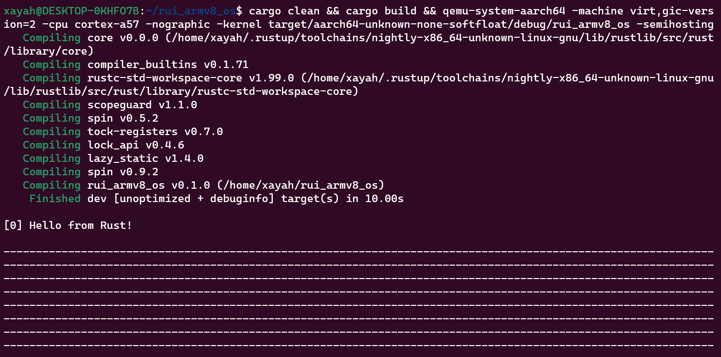
编译 并运行 ,测试 能否正常工作 。
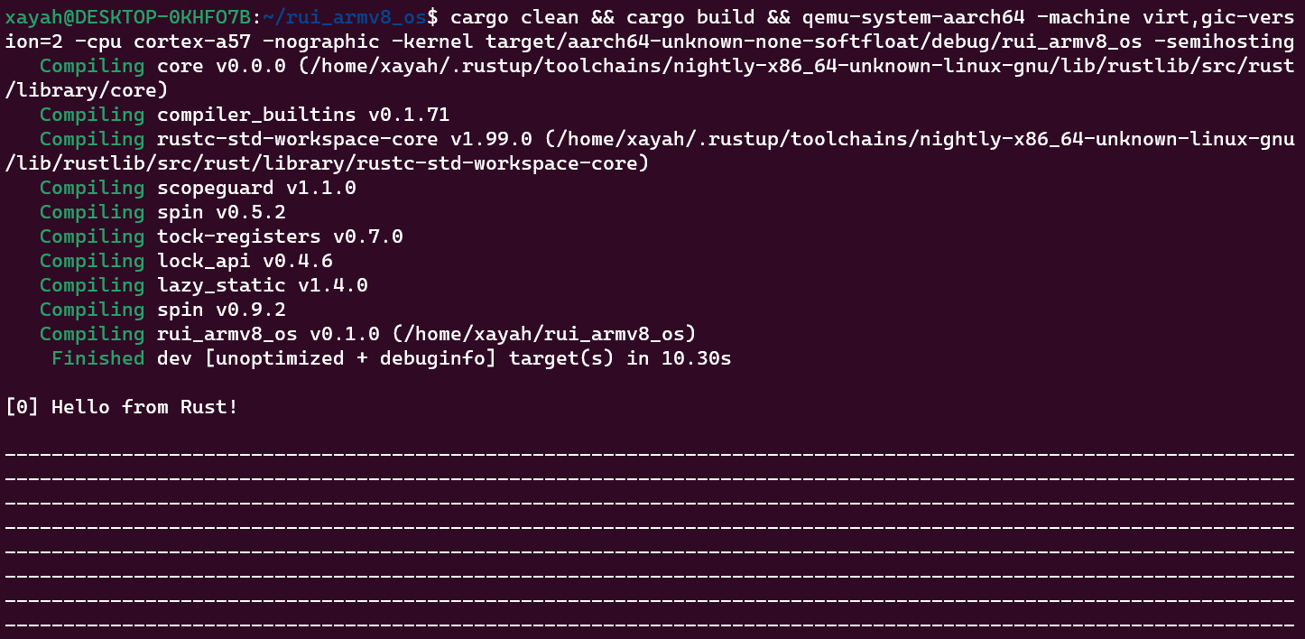
1 cargo clean && cargo build && qemu-system-aarch64 -machine virt,gic-version=2 -cpu cortex-a57 -nographic -kernel target/aarch64-unknown-none-softfloat/debug/rui_armv8_os -semihosting
正常运行!
二、使用Identity Mapping映射 - 偏移映射与页面共享
参考代码:下载
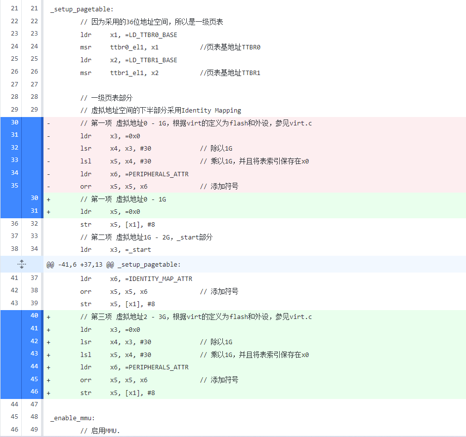
修改代码,将虚拟地址 2G - 3G处映射到物理地址 0 - 1G,从而对0x89000000 地址的写入将通过pl011 串口输出,因为此时0x89000000 映射到了物理地址pl011@9000000 。
编辑src/start.s,空白映射虚拟地址 0 - 1G,将虚拟地址 2G - 3G处映射到物理地址 0 - 1G。
1
2
3
4
5
6
7
8
9
10
11
12
13
14
15
16
17
18
19
20
21
22
23
24
25
26
27
28
// ······ _setup_pagetable: // 因为采用的36位地址空间,所以是一级页表 ldr x1, =LD_TTBR0_BASE msr ttbr0_el1, x1 //页表基地址TTBR0 ldr x2, =LD_TTBR1_BASE msr ttbr1_el1, x2 //页表基地址TTBR1 // 一级页表部分 // 虚拟地址空间的下半部分采用Identity Mapping // 第一项 虚拟地址0 - 1G ldr x5, =0x0 str x5, [x1], #8 // 第二项 虚拟地址1G - 2G,_start部分 ldr x3, =_start lsr x4, x3, #30 // 除以1G lsl x5, x4, #30 // 乘以1G,并且将表索引保存在x0 ldr x6, =IDENTITY_MAP_ATTR orr x5, x5, x6 // 添加符号 str x5, [x1], #8 // 第三项 虚拟地址2 - 3G,根据virt的定义为flash和外设,参见virt.c ldr x3, =0x0 lsr x4, x3, #30 // 除以1G lsl x5, x4, #30 // 乘以1G,并且将表索引保存在x0 ldr x6, =PERIPHERALS_ATTR orr x5, x5, x6 // 添加符号 str x5, [x1], #8 // ······
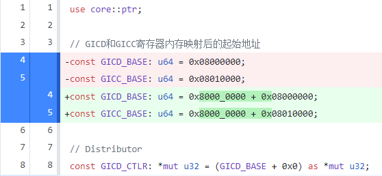
编辑src/interrupts.rs,修改其基址(2G+原基址)
1
2
3
4
5
6
7
8
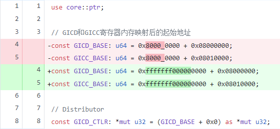
use core::ptr; // GICD和GICC寄存器内存映射后的起始地址 const GICD_BASE: u64 = 0x8000_0000 + 0x08000000; const GICC_BASE: u64 = 0x8000_0000 + 0x08010000; // Distributor // ······
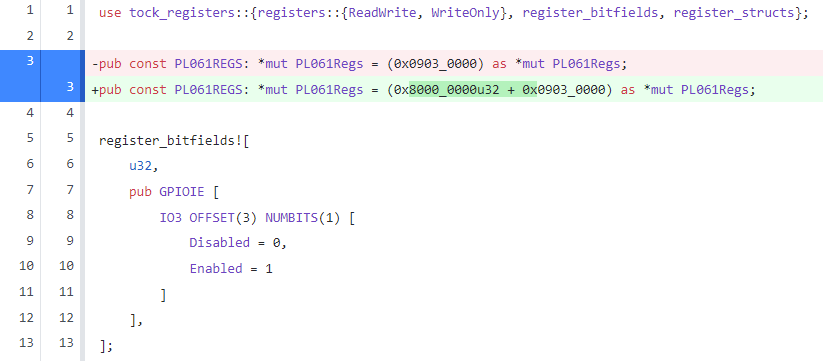
编辑src/pl061.rs,修改其基址(2G+原基址)
1
2
3
4
use tock_registers::{registers::{ReadWrite, WriteOnly}, register_bitfields, register_structs}; pub const PL061REGS: *mut PL061Regs = (0x8000_0000u32 + 0x0903_0000) as *mut PL061Regs; // ······
编辑src/uart_console/pl011.rs,修改其基址(2G+原基址)
1
2
3
4
use tock_registers::{registers::{ReadOnly, ReadWrite, WriteOnly}, register_bitfields, register_structs}; pub const PL011REGS: *mut PL011Regs = (0x8000_0000u32 +0x0900_0000) as *mut PL011Regs; // ······
编译 并运行 ,测试 能否正常工作 。
1 cargo clean && cargo build && qemu-system-aarch64 -machine virt,gic-version=2 -cpu cortex-a57 -nographic -kernel target/aarch64-unknown-none-softfloat/debug/rui_armv8_os -semihosting
正常运行!
三、使用非Identity Mapping映射 - 块级映射
参考代码:下载
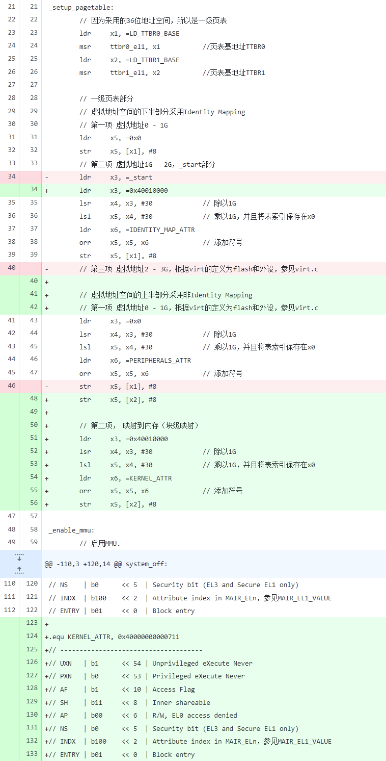
编辑src/start.s,处理虚拟地址空间 的上半部分 。
1
2
3
4
5
6
7
8
9
10
11
12
13
14
15
16
17
18
19
20
21
22
23
24
25
26
27
28
29
30
31
32
33
34
35
36
37
38
39
40
41
42
43
44
45
46
47
48
49
50
51
// ······ _setup_pagetable: // 因为采用的36位地址空间,所以是一级页表 ldr x1, =LD_TTBR0_BASE msr ttbr0_el1, x1 //页表基地址TTBR0 ldr x2, =LD_TTBR1_BASE msr ttbr1_el1, x2 //页表基地址TTBR1 // 一级页表部分 // 虚拟地址空间的下半部分采用Identity Mapping // 第一项 虚拟地址0 - 1G ldr x5, =0x0 str x5, [x1], #8 // 第二项 虚拟地址1G - 2G,_start部分 ldr x3, =0x40010000 lsr x4, x3, #30 // 除以1G lsl x5, x4, #30 // 乘以1G,并且将表索引保存在x0 ldr x6, =IDENTITY_MAP_ATTR orr x5, x5, x6 // 添加符号 str x5, [x1], #8 // 虚拟地址空间的上半部分采用非Identity Mapping // 第一项 虚拟地址0 - 1G,根据virt的定义为flash和外设,参见virt.c ldr x3, =0x0 // lsr x4, x3, #30 // 除以1G lsl x5, x4, #30 // 乘以1G,并且将表索引保存在x0 ldr x6, =PERIPHERALS_ATTR orr x5, x5, x6 // 添加符号 str x5, [x2], #8 // 第二项, 映射到内存(块级映射) ldr x3, =0x40010000 lsr x4, x3, #30 // 除以1G lsl x5, x4, #30 // 乘以1G,并且将表索引保存在x0 ldr x6, =KERNEL_ATTR orr x5, x5, x6 // 添加符号 str x5, [x2], #8 _enable_mmu: // ······ .equ KERNEL_ATTR, 0x40000000000711 // ------------------------------------- // UXN | b1 << 54 | Unprivileged eXecute Never // PXN | b0 << 53 | Privileged eXecute Never // AF | b1 << 10 | Access Flag // SH | b11 << 8 | Inner shareable // AP | b00 << 6 | R/W, EL0 access denied // NS | b0 << 5 | Security bit (EL3 and Secure EL1 only) // INDX | b100 << 2 | Attribute index in MAIR_ELn,参见MAIR_EL1_VALUE // ENTRY | b01 << 0 | Block entry
重构 aarch64-qemu.ld
1
2
3
4
5
6
7
8
9
10
11
12
13
14
15
16
17
18
19
20
21
22
23
24
25
26
27
28
29
30
31
32
33
34
35
36
37
38
39
40
41
42
43
44
45
46
47
48
49
50
__KERN_VMA_BASE = 0xfffffff000000000; __PHY_DRAM_START_ADDR = 0x40000000; __PHY_START_LOAD_ADDR = 0x40010000; ENTRY(__PHY_START_LOAD_ADDR) SECTIONS { . = __KERN_VMA_BASE + __PHY_START_LOAD_ADDR; .text.boot : AT(__PHY_START_LOAD_ADDR) { KEEP(*(.text.boot)) } .text : { *(.text*) } . = ALIGN(0x1000); LD_DATA_BASE = .; .data : { *(.data*) } . = ALIGN(0x1000); LD_RODATA_BASE = .; .rodata : { *(.rodata*) } . = ALIGN(0x1000); LD_BSS_BASE = .; .bss : { *(.bss*) . = ALIGN(4096); . += (4096 * 100); /* 栈的大小 */ stack_top = .; LD_STACK_PTR = .; } /* 页表 */ .pt : { . = ALIGN(4096); /* 页表基地址TTBR0 */ LD_TTBR0_BASE = . - __KERN_VMA_BASE; . = . + 0x1000; /* 页表基地址TTBR1 */ LD_TTBR1_BASE = . - __KERN_VMA_BASE; . = . + 0x1000; } . = . + 0x1000; LD_KERNEL_END = . - __KERN_VMA_BASE; }
编辑src/interrupts.rs,修改其基址(0xfffffff000000000+原基址)
1
2
3
4
5
6
7
8
use core::ptr; // GICD和GICC寄存器内存映射后的起始地址 const GICD_BASE: u64 = 0xfffffff000000000 + 0x08000000; const GICC_BASE: u64 = 0xfffffff000000000 + 0x08010000; // Distributor // ······
编辑src/pl061.rs,修改其基址(0xfffffff000000000+原基址)
1
2
3
4
use tock_registers::{registers::{ReadWrite, WriteOnly}, register_bitfields, register_structs}; pub const PL061REGS: *mut PL061Regs = (0xfffffff000000000u64 + 0x0903_0000) as *mut PL061Regs; // ······
编辑src/uart_console/pl011.rs,修改其基址(0xfffffff000000000+原基址)
1
2
3
4
use tock_registers::{registers::{ReadOnly, ReadWrite, WriteOnly}, register_bitfields, register_structs}; pub const PL011REGS: *mut PL011Regs = (0xfffffff000000000u64 + 0x0900_0000) as *mut PL011Regs; // ······
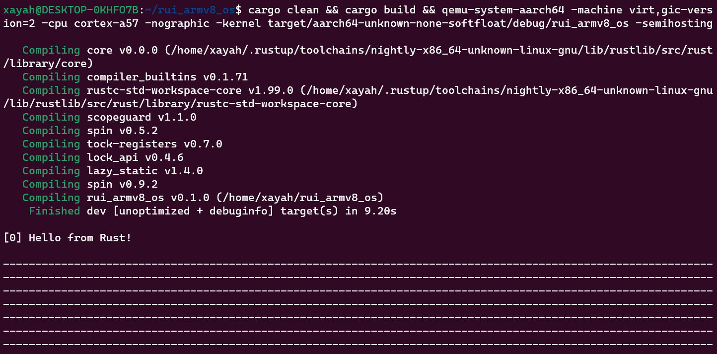
编译 并运行 ,测试 能否正常工作 。
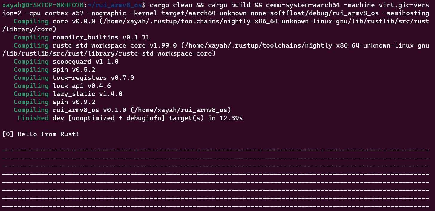
1 cargo clean && cargo build && qemu-system-aarch64 -machine virt,gic-version=2 -cpu cortex-a57 -nographic -kernel target/aarch64-unknown-none-softfloat/debug/rui_armv8_os -semihosting
正常运行!
修复异常现象
参考代码:下载
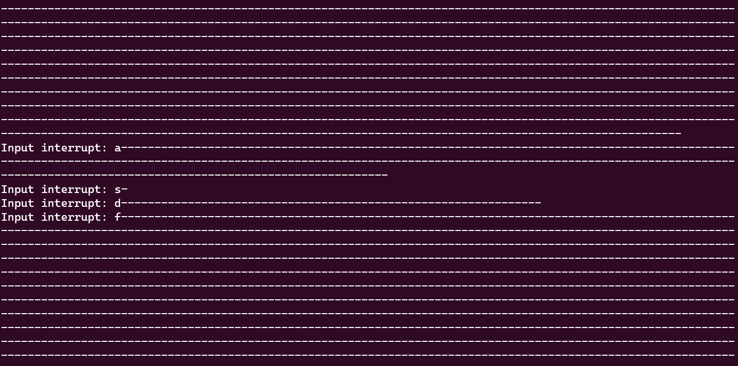
乍一看能正常运行 ,但是运行一段时间后居然卡死 了!这是为什么 呢?
第一时间 想到的是互斥锁 可能出问题了,但是仔细看互斥锁 的代码 发现和内存映射 关系应该不大。
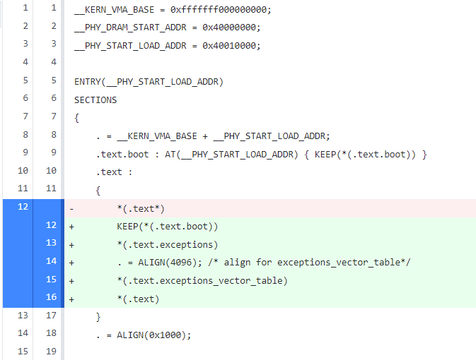
仔细观察输出 发现打点 是正常 的,而且在没有卡死之前 如果触发输入中断 则会立刻卡死 ,因此判断是输入中断 出了问题, noionion 链接脚本 的问题,而事实 也如他所说。
编辑aarch64-qemu.ld,修改.text : {}部分:
1
2
3
4
5
6
7
8
9
10
11
12
/* ······ */ .text.boot : AT(__PHY_START_LOAD_ADDR) { KEEP(*(.text.boot)) } .text : { KEEP(*(.text.boot)) *(.text.exceptions) . = ALIGN(4096); /* align for exceptions_vector_table*/ *(.text.exceptions_vector_table) *(.text) } . = ALIGN(0x1000); /* ······ */
编译 并运行 ,测试 能否正常工作 。
1 cargo clean && cargo build && qemu-system-aarch64 -machine virt,gic-version=2 -cpu cortex-a57 -nographic -kernel target/aarch64-unknown-none-softfloat/debug/rui_armv8_os -semihosting
正常运行!
四、使用非Identity Mapping映射 - 页表映射
参考代码:下载
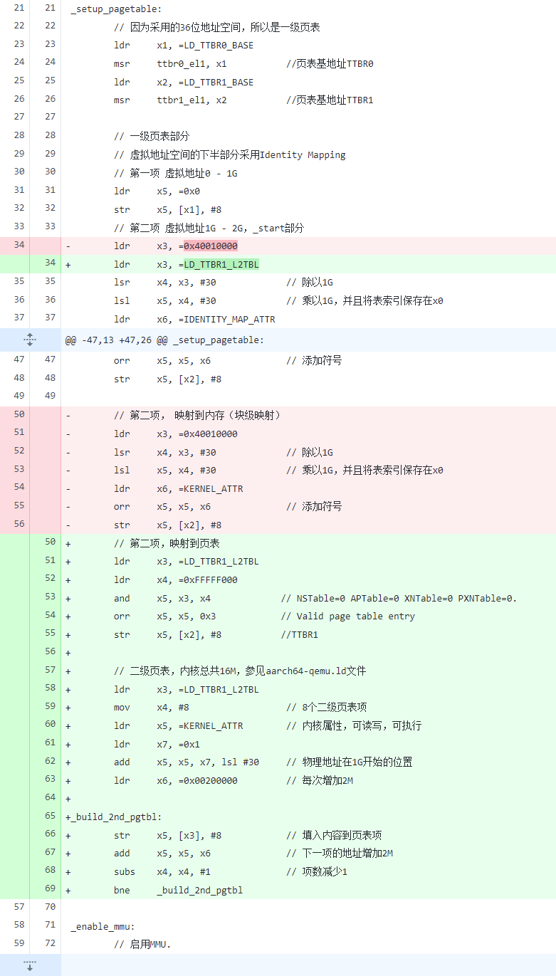
在成功实现块级映射 后,我们就可以尝试实现二级页表映射 了。src/start.s,修改块级映射 为二级页表映射 。
1
2
3
4
5
6
7
8
9
10
11
12
13
14
15
16
17
18
19
20
21
22
23
24
25
26
27
28
29
30
31
32
33
34
35
36
37
38
39
40
41
42
43
44
45
46
47
48
49
50
51
52
53
// ······ _setup_pagetable: // 因为采用的36位地址空间,所以是一级页表 ldr x1, =LD_TTBR0_BASE msr ttbr0_el1, x1 //页表基地址TTBR0 ldr x2, =LD_TTBR1_BASE msr ttbr1_el1, x2 //页表基地址TTBR1 // 一级页表部分 // 虚拟地址空间的下半部分采用Identity Mapping // 第一项 虚拟地址0 - 1G ldr x5, =0x0 str x5, [x1], #8 // 第二项 虚拟地址1G - 2G,_start部分 ldr x3, =LD_TTBR1_L2TBL lsr x4, x3, #30 // 除以1G lsl x5, x4, #30 // 乘以1G,并且将表索引保存在x0 ldr x6, =IDENTITY_MAP_ATTR orr x5, x5, x6 // 添加符号 str x5, [x1], #8 // 虚拟地址空间的上半部分采用非Identity Mapping // 第一项 虚拟地址0 - 1G,根据virt的定义为flash和外设,参见virt.c ldr x3, =0x0 lsr x4, x3, #30 // 除以1G lsl x5, x4, #30 // 乘以1G,并且将表索引保存在x0 ldr x6, =PERIPHERALS_ATTR orr x5, x5, x6 // 添加符号 str x5, [x2], #8 // 第二项,映射到页表 ldr x3, =LD_TTBR1_L2TBL ldr x4, =0xFFFFF000 and x5, x3, x4 // NSTable=0 APTable=0 XNTable=0 PXNTable=0. orr x5, x5, 0x3 // Valid page table entry str x5, [x2], #8 //TTBR1 // 二级页表,内核总共16M,参见aarch64-qemu.ld文件 ldr x3, =LD_TTBR1_L2TBL mov x4, #8 // 8个二级页表项 ldr x5, =KERNEL_ATTR // 内核属性,可读写,可执行 ldr x7, =0x1 add x5, x5, x7, lsl #30 // 物理地址在1G开始的位置 ldr x6, =0x00200000 // 每次增加2M _build_2nd_pgtbl: str x5, [x3], #8 // 填入内容到页表项 add x5, x5, x6 // 下一项的地址增加2M subs x4, x4, #1 // 项数减少1 bne _build_2nd_pgtbl _enable_mmu: // ······
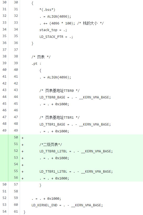
编辑aarch64-qemu.ld,定义LD_TTBR0_L2TBL以及LD_TTBR1_L2TBL符号
1
2
3
4
5
6
7
8
9
10
11
12
13
14
15
16
17
18
19
20
21
22
/* ······ */ /* 页表 */ .pt : { . = ALIGN(4096); /* 页表基地址TTBR0 */ LD_TTBR0_BASE = . - __KERN_VMA_BASE; . = . + 0x1000; /* 页表基地址TTBR1 */ LD_TTBR1_BASE = . - __KERN_VMA_BASE; . = . + 0x1000; /*二级页表*/ LD_TTBR0_L2TBL = . - __KERN_VMA_BASE; . = . + 0x1000; LD_TTBR1_L2TBL = . - __KERN_VMA_BASE; . = . + 0x1000; } /* ······ */
编译 并运行 ,测试 能否正常工作 。
1 cargo clean && cargo build && qemu-system-aarch64 -machine virt,gic-version=2 -cpu cortex-a57 -nographic -kernel target/aarch64-unknown-none-softfloat/debug/rui_armv8_os -semihosting
正常运行!
后记 前前后后花了三个月时间 完成了这篇1.6W 字的笔记,最大 的感悟 却是:自己的挖的坑只能含泪填完 。





![enter_into_os image]()
![ARMGIC image]()
![gicv2-logic image]()
![aarch64_exception_levels_2 image]()
.png)
2.png)








![gpio-poweroff image]()





![v2p-translate image]()
